
Cooling system based on evaporative cooling technology

An evaporative cooling and technology technology, applied in air conditioning systems, heating methods, lighting and heating equipment, etc., can solve the problems of human discomfort, wind blowing, and high energy consumption

Active Publication Date: 2020-05-29
XI'AN POLYTECHNIC UNIVERSITY
View PDF7 Cites 0 Cited by
  • Summary
  • Abstract
  • Description
  • Claims
  • Application Information

AI Technical Summary

Problems solved by technology

[0002] With the advancement of science and technology and the improvement of people's awareness of energy conservation and environmental protection, in order to solve the problems of high energy consumption of traditional air conditioners and "sick building syndrome", workstation air conditioners have emerged as the times require, but for the existing desktop workstation air supply system case After analyzing and summarizing, there are still some problems. There are two main problems. 1. The air supply end of the desktop station is close to the human head, which will produce a sense of blowing, causing discomfort to the human body. 2. The air supply of the desktop station is mechanically refrigerated. The cold air produced by the technology, although the amount of cold air required for desktop air supply is less, the energy consumption is reduced compared with the traditional air conditioner, but the energy consumption of the mechanical refrigeration technology itself is relatively high

Method used


Image

  • Cooling system based on evaporative cooling technology
  • Cooling system based on evaporative cooling technology
  • Cooling system based on evaporative cooling technology

Examples


Embodiment Construction

[0021] The present invention will be described in detail below in conjunction with the accompanying drawings and specific embodiments.

[0022] The present invention is a cooling system based on evaporative cooling technology, including a cold water part and a heat exchange part;

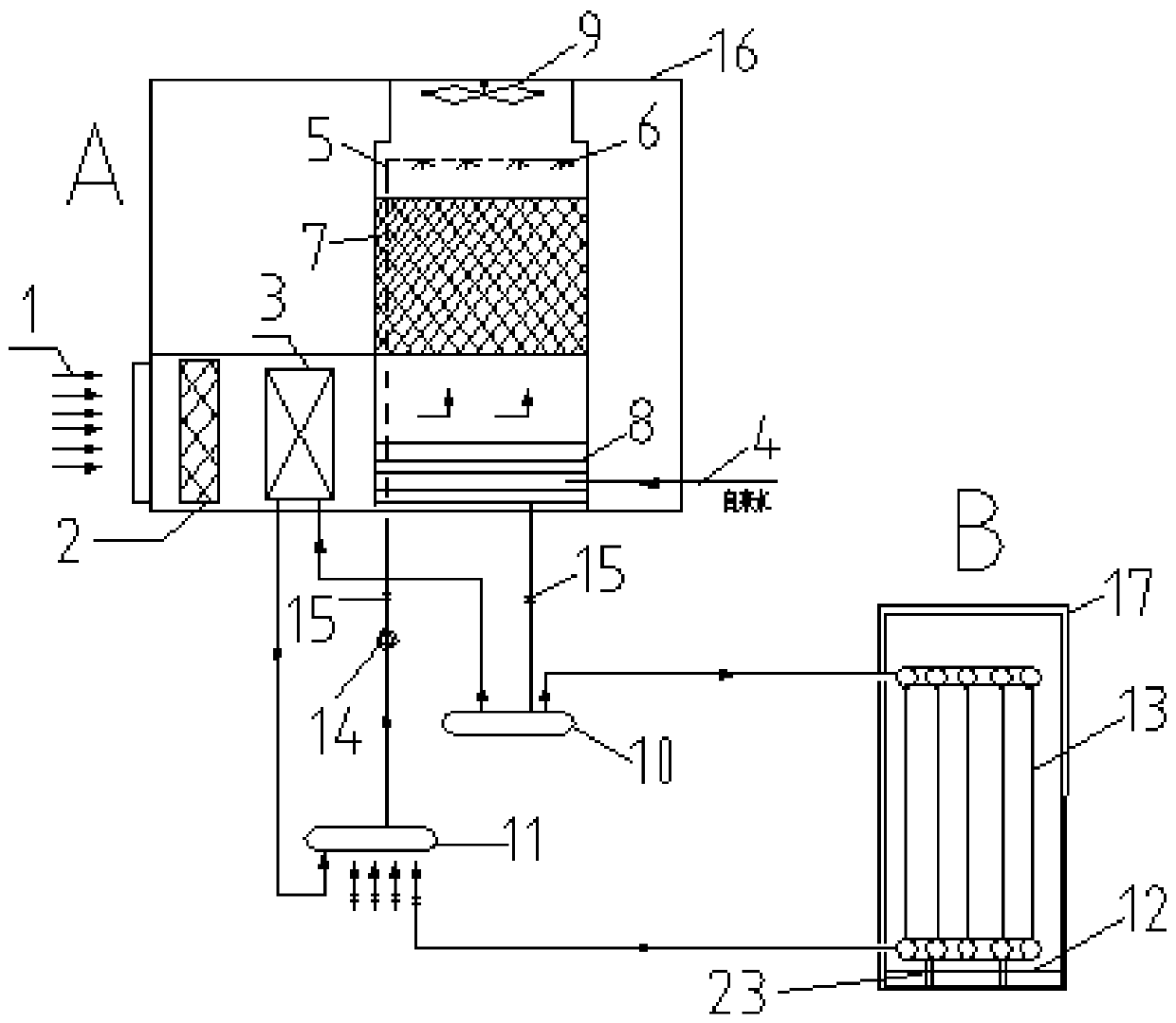
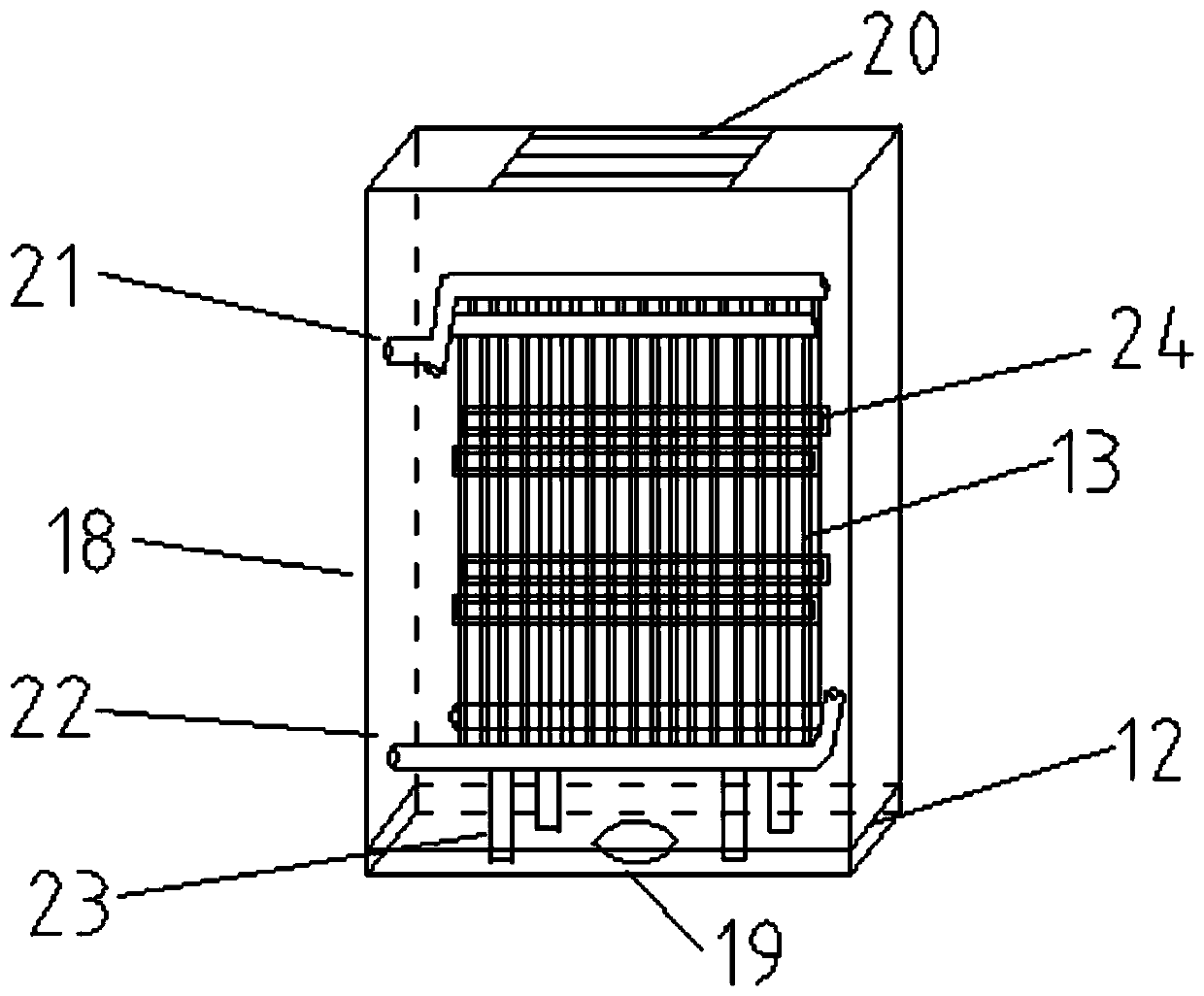
[0023] The cold water part includes an air inlet pipe 1, an air cooler 3, a water tank 8, and a water pipe 4 connected in sequence. The bottom of the water tank 8 is connected to the inlet of the water separator 10 through a pipe, and the outlet of the water separator 10 is respectively connected to pipe a and pipe b. The heat release part of the air cooler 3 is connected to the water collector 11, the pipe b is connected to the heat exchange part, the upper part of the water tank 8 is connected to a plurality of nozzles 6, the inside of the water tank 8 is connected to the filler 7, and the plurality of nozzles 6 are connected to the spray pipe 5, The spray pipe 5 is sequentially connected to the w...


PUM


Abstract

The invention discloses a cooling system based on an evaporative cooling technology. The cooling system comprises a cold water part and a heat exchange part, wherein the cold water part comprises an air inlet pipe, an air cooler, a water tank and a water pipe which are sequentially connected; the bottom of the water tank is connected with an inlet of a water distributor through a pipeline; an outlet of the water distributor is connected with a pipeline a and a pipeline b; the pipeline a penetrates a heat release part of the air cooler to be connected with a water collector; the pipeline b is connected with the heat exchange part; a plurality of nozzles are connected to the upper part in the water tank; filler is connected in the water tank; the plurality of nozzles are sequentially connected with a water pump and a water collector water outlet through spraying pipes; the heat exchange part comprises a housing and a cold water channel in the housing; one end of the cold water channel isconnected with the water distributor through the pipeline b, and the other end of the cold water channel is connected with the water collector; and an air supply opening is formed in the bottom of the housing. According to the cooling system, cold water is prepared through the environment-friendly, economical and efficient evaporative cooling technology, low energy consumption and a special tabletop air supply manner are achieved, the air blowing feeling is eliminated, and the human body comfort degree is improved.

Description

technical field [0001] The invention belongs to the technical field of refrigeration equipment, and in particular relates to a cooling system based on evaporative cooling technology. Background technique [0002] With the advancement of science and technology and the improvement of people's awareness of energy conservation and environmental protection, in order to solve the problems of high energy consumption of traditional air conditioners and "sick building syndrome", workstation air conditioners have emerged as the times require, but the existing desktop workstation air supply system case After analyzing and summarizing, there are still some problems. There are two main problems. 1. The air supply end of the desktop station is close to the human head, which will cause a sense of blowing, causing discomfort to the human body. 2. The air supply of the desktop station is mechanically refrigerated. Although the cold air produced by the technology requires less cold air for de...

Claims


Application Information

Patent Timeline
IPC IPC(8): F24F5/00F24F13/14F24F13/20F24F13/28F24F13/30F24F13/32
CPCF24F5/0035F24F13/28F24F13/30F24F13/20F24F13/32F24F13/14
Inventor 王丽娟孔培婷
Owner XI'AN POLYTECHNIC UNIVERSITY
Learn More