Digital display measuring device for subway contact rail

A technology of measuring devices and contact rails, applied in measuring devices, mechanical measuring devices, mechanical devices, etc., can solve the problems of difficult to guarantee the accuracy of measurement data, slow measurement efficiency, and bulky structure, and achieve light weight, easy disassembly, The effect of ensuring measurement accuracy

Pending Publication Date: 2020-05-29
ELECTRICAL ENG CO LTD OF CTCE GRP +1
View PDF0 Cites 0 Cited by
  • Summary
  • Abstract
  • Description
  • Claims
  • Application Information

AI Technical Summary

Problems solved by technology

[0002] In the measurement of the guide height and pull-out value of the subway catenary rail, two tools, the subway catenary rail inspection vehicle or the catenary rail measuring ruler, are usually used at present. The subway catenary rail inspection vehicle has disadvantages such as high cost, heavy structure, and slow measurement efficiency. Therefore, more portable contact rail measuring rulers are used. The contact rail has the characteristics of low working surface, and its guide height (that is, the vertical distance from the rail surface to the rail surface) is about 200mm. It is required that the installation accuracy error be controlled within ± 3mm. Use the contact rail When measuring the track ruler, the surveyor usually needs to lean over to measure, and the measured data is overlooking data, which has a certain error with the real data, and the accuracy of the measurement data is difficult to guarantee

Method used


Image

  • Digital display measuring device for subway contact rail
  • Digital display measuring device for subway contact rail
  • Digital display measuring device for subway contact rail

Examples


Embodiment Construction

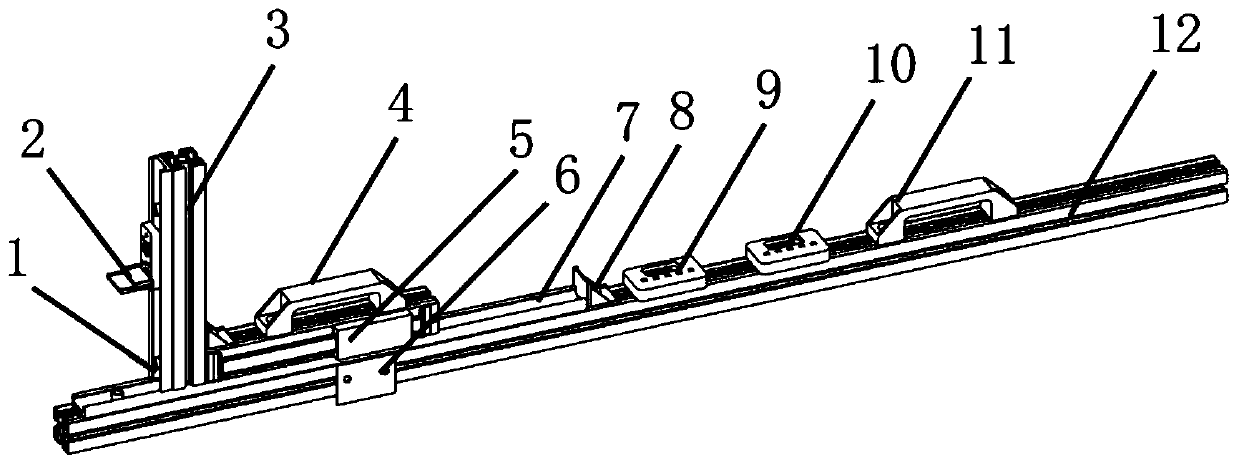
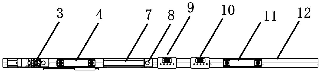
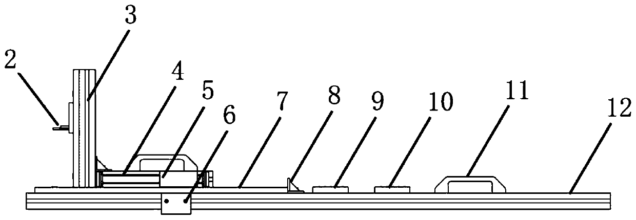
[0020] Such as figure 1 , 2 , shown in 3, a kind of metro contact rail digital display measuring device comprises a support base 12, a measurement guide rail 7 is fixedly installed on the support base 12, and a sliding measurement platform 4 is installed on the measurement guide rail 7 for sliding cooperation. The left end of the measuring platform 4 is fixedly equipped with a vertical support rod 3, and a digital caliper 1 5 is horizontally installed on the front side of the sliding measurement platform 4, and a digital caliper 2 2 is vertically installed on the left side of the vertical support rod 3, The digital caliper one 5 and the digital caliper two 2 are electrically connected to the digital caliper display part one 9 and the digital caliper display part two 10 respectively.

[0021] A base clip 6 is fixed on the side of the support base 12 . The base clamp is a plastic plate with a card edge at the lower end, which is used to clamp the steel rail.

[0022] Both the...


PUM


Abstract

The invention discloses a digital display measuring device for a subway contact rail. The device comprises a supporting base. A measuring guide rail is fixedly mounted on the supporting base. A sliding measurement platform is mounted on the measurement guide rail in a sliding fit manner. A vertical supporting rod is fixedly installed at the left end of the sliding measurement platform, a first digital caliper is horizontally installed on the front side face of the sliding measurement platform, a second digital caliper is vertically installed on the left side face of the vertical supporting rod, and the first digital caliper and the second digital caliper are electrically connected with a first digital caliper display part and a second digital caliper display part respectively. The device is reasonable in structural design, and the contact rail measurement operation can be efficiently completed, and measurement of contact rail height and pull-out value of different sections can be satisfied. The device is light in weight, easy to disassemble, low in manufacturing cost, simple and practical, manual reading of traditional measurement is changed into data directly reflected in a digital display scaleplate interface, errors caused by manual reading are avoided, the measurement precision is guaranteed, and the measurement efficiency is improved.

Description

technical field [0001] The invention relates to the technical field necessary for the measurement of the guide height and pull-out value of a subway contact rail, in particular to a digital display measuring device for a subway contact rail. Background technique [0002] In the measurement of the guide height and pull-out value of the subway catenary rail, two tools, the subway catenary rail inspection vehicle or the catenary rail measuring ruler, are usually used at present. The subway catenary rail inspection vehicle has disadvantages such as high cost, heavy structure, and slow measurement efficiency. Therefore, more portable contact rail measuring rulers are used. The contact rail has the characteristics of low working surface, and its guide height (that is, the vertical distance from the rail surface to the rail surface) is about 200mm. It is required that the installation accuracy error be controlled within ± 3mm. Use the contact rail When measuring the track ruler, th...

Claims


Application Information

Patent Timeline
Patent Type & Authority Applications(China)
IPC IPC(8): G01B5/00G01B5/02G01B5/06
CPCG01B5/00G01B5/02G01B5/061
Inventor 王熹陈青松袁群虎李国政郝坤郑一鸣何康平
Owner ELECTRICAL ENG CO LTD OF CTCE GRP
Why Eureka
Try Eureka