A Demodulation Method of Differential Circular Inductor Synchronizer

A technology of circular induction synchronizer and demodulation method, which is applied in the field of sensors, can solve the problems that the accuracy can only reach angle classification, determine the number of cycles, and be easily affected by temperature, etc., and achieve zero drift, accurate measurement, and high-precision measurement Effect

Active Publication Date: 2022-04-05
SHANGHAI AEROSPACE CONTROL TECH INST
View PDF5 Cites 0 Cited by
  • Summary
  • Abstract
  • Description
  • Claims
  • Application Information

AI Technical Summary

Problems solved by technology

Traditional inductosynchronizers usually have two sets of windings, which are independent of each other, and are generally called coarse channel and fine channel; the fine channel has multiple pairs of poles, and the accuracy can reach the order of arc seconds; Angle-graded and unique null easily affected by temperature
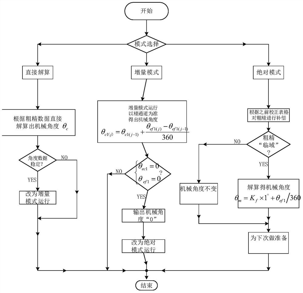
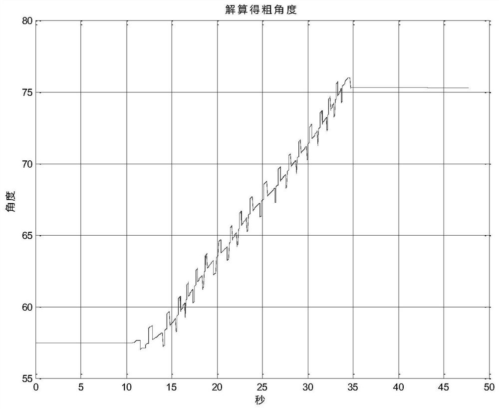
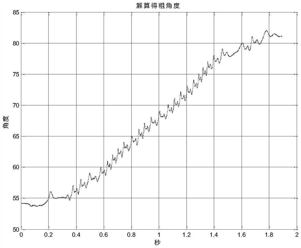
In order to overcome this shortcoming, a differential circular induction synchronizer came into being. Its biggest advantage is that the zero position of the coarse and fine channels is not affected by temperature, and the accuracy of the coarse channel can also reach the order of arc seconds, but the coarse channel is not like the traditional The type inductive synchronizer has only 1 pair of poles, and it is also multi-pole, usually only 1 pair of poles less than the fine channel, so the coarse channel cannot use it to directly determine the number of cycles, it also needs the angle data of the fine channel, through the coarse and fine channel The angle data of the channel is calculated to obtain its cycle number. After the cycle number is obtained, it is combined with the fine channel data to obtain the mechanical absolute angle. In addition, due to the processing technology of the rough and fine channels, it is impossible to ensure that the rough and fine channels are strictly linear, resulting in The combined mechanical angle is not continuous, smooth, or even has periodic jumps, which results in a decrease in the performance of the servo control system, or even out of control. Therefore, the coarse and fine channels must be corrected, and when combining the mechanical absolute angle data, it is necessary to It is determined according to whether the coarse and fine data are "adjacent", so it is necessary to design a demodulation or solution method based on a differential circular induction synchronizer

Method used


Image

  • A Demodulation Method of Differential Circular Inductor Synchronizer
  • A Demodulation Method of Differential Circular Inductor Synchronizer
  • A Demodulation Method of Differential Circular Inductor Synchronizer

Examples


Embodiment Construction

[0042] The following is attached Figures 1 to 9and specific embodiments The demodulation method, sub-equipment and storage medium of a differential circular inductive synchronizer proposed by the present invention will be further described in detail. The advantages and features of the present invention will become clearer from the following description. It should be noted that the drawings are in a very simplified form and all use imprecise scales, which are only used to facilitate and clearly assist the purpose of illustrating the embodiments of the present invention. In order to make the objects, features and advantages of the present invention more comprehensible, please refer to the accompanying drawings. It should be noted that the structures, proportions, sizes, etc. shown in the drawings attached to this specification are only used to match the content disclosed in the specification, for those who are familiar with this technology to understand and read, and are not u...


PUM


Abstract

The invention discloses a demodulation method of a differential circular induction synchronizer. Each cycle of the electric angle in the value interval and each cycle of the main value interval electric angle of the fine channel are compensated and corrected synchronously, and the corrected main value interval electric angle of the coarse channel and the main value interval electric angle of the fine channel are obtained; according to the corrected The electrical angle of the main value interval of the coarse channel and the electrical angle of the main value interval of the fine channel obtain the second mechanical angle; according to the preset conditions, judge the electrical angle of the main value interval of the corrected coarse channel and the main value interval of the corrected fine channel Whether the electrical angle is adjacent, the cycle number of the fine channel electrical angle is obtained according to the judgment result and the second mechanical angle; the third mechanical angle is obtained according to the cycle number of the fine channel electrical angle and the corrected main value interval electrical angle of the fine channel. The invention improves the measurement accuracy of the mechanical angle.

Description

technical field [0001] The invention relates to the technical field of sensors, in particular to a demodulation method of a differential circular induction synchronizer. Background technique [0002] In the high-precision control moment gyroscope and turntable control system, the angle measurement system is a key component. The circular induction synchronizer is an electromagnetic induction sensing element used to detect the mechanical rotation angle. It is essentially a planar winding multi-pole resolver. Due to a series of advantages such as small size, light weight, impact resistance, radiation resistance, and high vacuum resistance, it has been widely used in harsh environmental conditions, and its application in aerospace has become more prominent in recent years. Traditional inductosynchronizers usually have two sets of windings, which are independent of each other, and are generally called coarse channel and fine channel; the fine channel has multiple pairs of poles,...

Claims


Application Information

Patent Timeline
Patent Type & Authority Patents(China)
IPC IPC(8): G01C1/00G01C25/00G06F17/18
CPCG01C1/00G01C25/005G06F17/18
Inventor 黎枭魏新生周华俊杨杰孙丹峰
Owner SHANGHAI AEROSPACE CONTROL TECH INST
Why Eureka
Try Eureka