A method and system for estimating the temperature of the rotor magnet of a permanent magnet synchronous motor

A permanent magnet synchronous motor and rotor technology, applied in the control system, control generator, vector control system, etc., can solve the problems of large rotor temperature error, difficult thermal management of motor rotor, magnetic steel demagnetization, etc., to improve torque output Accuracy, demagnetization prevention, and reliability improvement effects

Active Publication Date: 2021-09-24
ZHUZHOU CSR TIMES ELECTRIC CO LTD
View PDF15 Cites 0 Cited by
  • Summary
  • Abstract
  • Description
  • Claims
  • Application Information

AI Technical Summary

Problems solved by technology

Among them, the magnet steel of the permanent magnet synchronous motor is a heat-sensitive material, and its magnetic energy product curve is related to temperature. Therefore, changes in the temperature of the magnet steel often lead to poor torque accuracy, and when the temperature reaches a certain value, the magnet steel will also appear irreversible. Demagnetization phenomenon, causing permanent damage to the motor
[0003] Magnetic steel is generally embedded on the rotor of the motor, making it difficult to measure directly with a general temperature sensor, making the thermal management of the motor rotor difficult
[0004] In the existing on-line method for estimating the rotor magnet temperature of permanent magnet synchronous motors, the following three methods are often used for estimation: first, by establishing the rotor loss model, the stator loss model, and the rotor thermal model, the Real-time calculation of the rotor temperature of the motor, but this method does not take into account the heat dissipation during the operation of the rotor into the actual energy loss of the rotor, which has a great impact on the rotor temperature of the motor, especially when the rotor temperature is in the high temperature zone. Seriously affect the estimation accuracy; second, observe the rotor temperature based on the rotor resistance of the induction motor, but for the permanent magnet synchronous motor, there is no rotor resistance, so this method cannot be extended to the permanent magnet synchronous motor; third, according to the motor The voltage equation model calculates the flux linkage and reverses the rotor temperature, but in fact the motor model is a multi-coupled nonlinear system, and the motor model will change greatly in different operating states of the motor. The flux linkage is calculated, so the error of the calculated rotor temperature is large

Method used


Image

  • A method and system for estimating the temperature of the rotor magnet of a permanent magnet synchronous motor
  • A method and system for estimating the temperature of the rotor magnet of a permanent magnet synchronous motor
  • A method and system for estimating the temperature of the rotor magnet of a permanent magnet synchronous motor

Examples


Embodiment 1

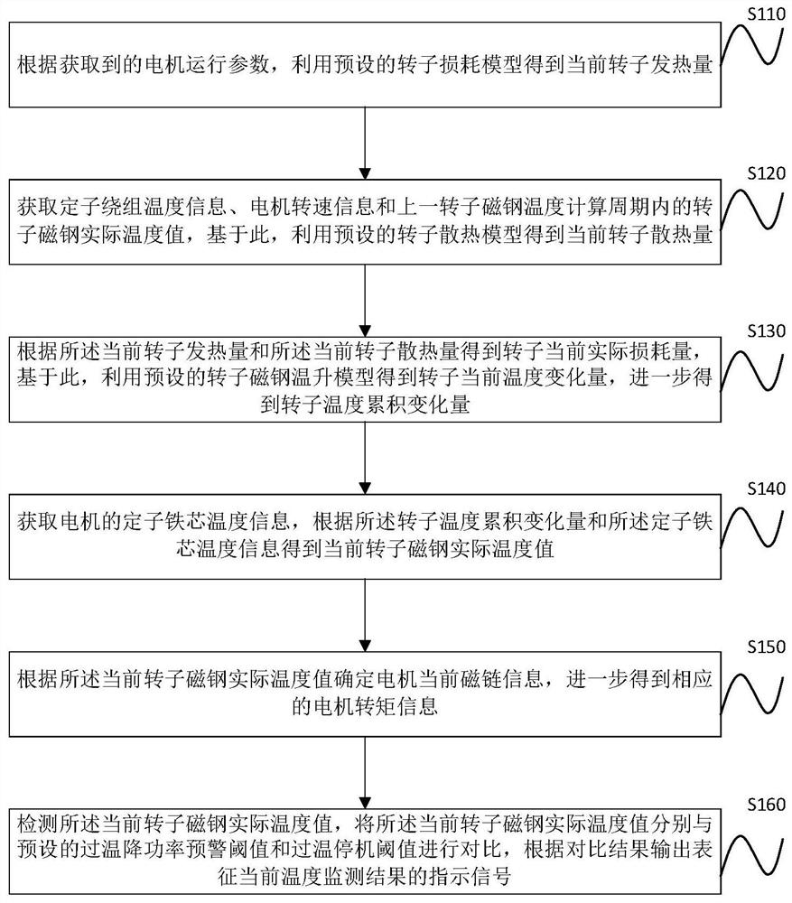
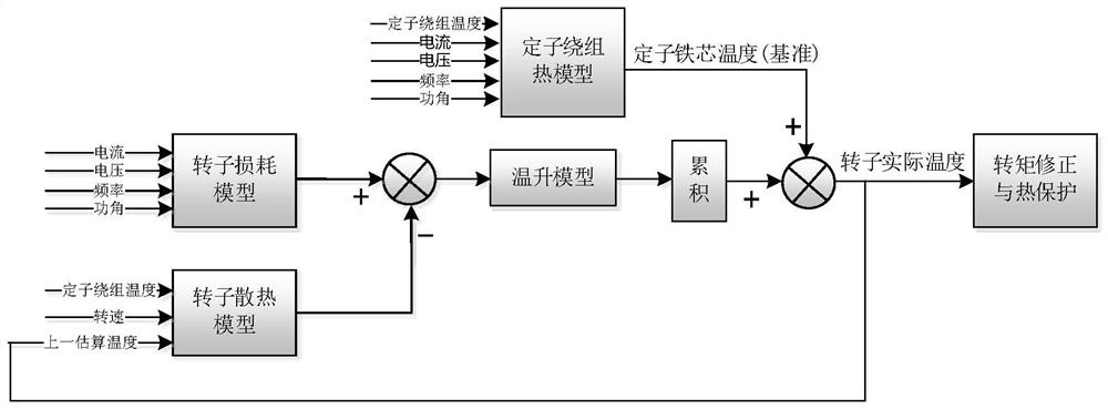
[0026] figure 1 It is a step chart of the method for online estimation of the temperature of the rotor magnetic steel of the permanent magnet synchronous motor according to the embodiment of the present application. figure 2 It is a schematic diagram of the principle of the method for online estimation of the temperature of the rotor magnetic steel of the permanent magnet synchronous motor according to the embodiment of the present application. Combine below figure 1 and figure 2 The online estimation method for the temperature of the rotor magnetic steel of the permanent magnet synchronous motor in the embodiment of the present invention will be described.

[0027] In step S110, the motor operating parameters are obtained, and the current calorific value of the rotor is obtained by using a preset rotor loss model according to the motor operating parameters obtained in real time. Wherein, the motor operating parameters at least include: current information, voltage inform...

Embodiment 2

[0049] refer again figure 1 and figure 2 , after obtaining the actual rotor magnet temperature value in the current rotor magnet temperature calculation period through the above steps S110 to S140, enter into step S150.

[0050] In step S150, the current flux linkage information of the motor is determined according to the actual rotor magnet temperature value in the current rotor magnet temperature calculation period, and the corresponding motor torque information is further obtained. Specifically, determine the corresponding magnetic energy product curve according to the material of the rotor magnet, and further determine the preset temperature flux linkage change relationship curve corresponding to the magnetic energy product curve; according to the actual temperature value of the rotor magnet steel, use the temperature flux linkage change relationship curve , get the current flux information of the motor, and further get the torque information of the motor.

[0051]Furth...

Embodiment 3

[0056] refer again figure 1 and figure 2 After obtaining the actual temperature value of the rotor magnet steel in the current calculation period of the rotor magnet steel temperature through the above steps S110 to S140, it further enters step S160. In step S160, the current actual temperature value of the rotor magnet is detected, and the current actual temperature value of the rotor magnet is compared with the preset over-temperature warning threshold, over-temperature drop power warning threshold and over-temperature shutdown threshold, respectively. According to the comparison results, An indication signal representing the current temperature monitoring result is output. Further, the corresponding indication signal is sent to the motor driving device in the motor controller, so as to control the motor driving device to operate in combination with the above indication signal. Furthermore, through devices such as relevant indicator lights or displays connected to the mot...


PUM


Abstract

The invention discloses a method for estimating the temperature of the rotor magnetic steel of a permanent magnet synchronous motor. Based on the actual temperature value of the rotor magnet steel in the last rotor magnet temperature calculation cycle, the current rotor heat dissipation is obtained by using the preset rotor heat dissipation model; the current actual loss of the rotor is obtained according to the current rotor heat generation and the current rotor heat dissipation, Based on this, the current temperature change of the rotor is obtained by using the preset rotor magnet temperature rise model, and the cumulative change of the rotor temperature is further obtained; the stator core temperature information of the motor is obtained, and the current temperature is obtained according to the cumulative change of the rotor temperature and the stator core temperature. The actual temperature value of the rotor magnet. The invention improves the estimation accuracy of the rotor temperature, effectively prevents the demagnetization phenomenon caused by the overheating of the permanent magnet magnetic steel, and improves the reliability and utilization rate of the motor.

Description

technical field [0001] The invention relates to the technical field of motor control, in particular to a method and system for estimating the temperature of a rotor magnetic steel of a permanent magnet synchronous motor. Background technique [0002] With the widespread application of electric vehicles, more and more vehicles adopt electric drive solutions. As the power source of electric vehicles, the performance of the motor directly determines the driving experience of the vehicle. In order to obtain a higher cruising range, the power density of the motor, battery, and electronic control is getting bigger and bigger, and it also puts forward higher requirements for the thermal management of the entire system. Among them, the magnet steel of the permanent magnet synchronous motor is a heat-sensitive material, and its magnetic energy product curve is related to temperature. Therefore, changes in the temperature of the magnet steel often lead to poor torque accuracy, and wh...

Claims


Application Information

Patent Timeline
Patent Type & Authority Patents(China)
IPC IPC(8): H02P21/14
CPCH02P21/14
Inventor 陈建明刘旺周成陈磊何伟李靖张宇翔陈昆孙博文杨印博李飞建
Owner ZHUZHOU CSR TIMES ELECTRIC CO LTD
Why Eureka
Try Eureka