Test mold assembly device

A technology for assembly equipment and mold testing, which is applied to metal processing equipment, assembly machines, spraying devices, etc., can solve the problems of high work intensity and low efficiency of operators, and achieve the effects of improving work efficiency, improving precision, and reducing work intensity

Pending Publication Date: 2020-06-02
NANJING SINOTEST ROBOTICS CO LTD
View PDF0 Cites 0 Cited by
  • Summary
  • Abstract
  • Description
  • Claims
  • Application Information

AI Technical Summary

Problems solved by technology

[0004] The purpose of the present invention is to provide a trial mold assembly equipment to alleviate the technical problem existing in the prior art that completely relying on manual assembly of the trial mold makes the operator's work intensity relatively high and the efficiency low

Method used


Image

  • Test mold assembly device
  • Test mold assembly device
  • Test mold assembly device

Examples


Embodiment Construction

[0044] In order to make the purpose, technical solutions and advantages of the embodiments of the present invention clearer, the technical solutions in the embodiments of the present invention will be clearly and completely described below in conjunction with the drawings in the embodiments of the present invention. Obviously, the described embodiments It is a part of embodiments of the present invention, but not all embodiments. The components of the embodiments of the invention generally described and illustrated in the figures herein may be arranged and designed in a variety of different configurations.

[0045] Accordingly, the following detailed description of the embodiments of the invention provided in the accompanying drawings is not intended to limit the scope of the claimed invention, but merely represents selected embodiments of the invention. Based on the embodiments of the present invention, all other embodiments obtained by persons of ordinary skill in the art wi...


PUM


Abstract

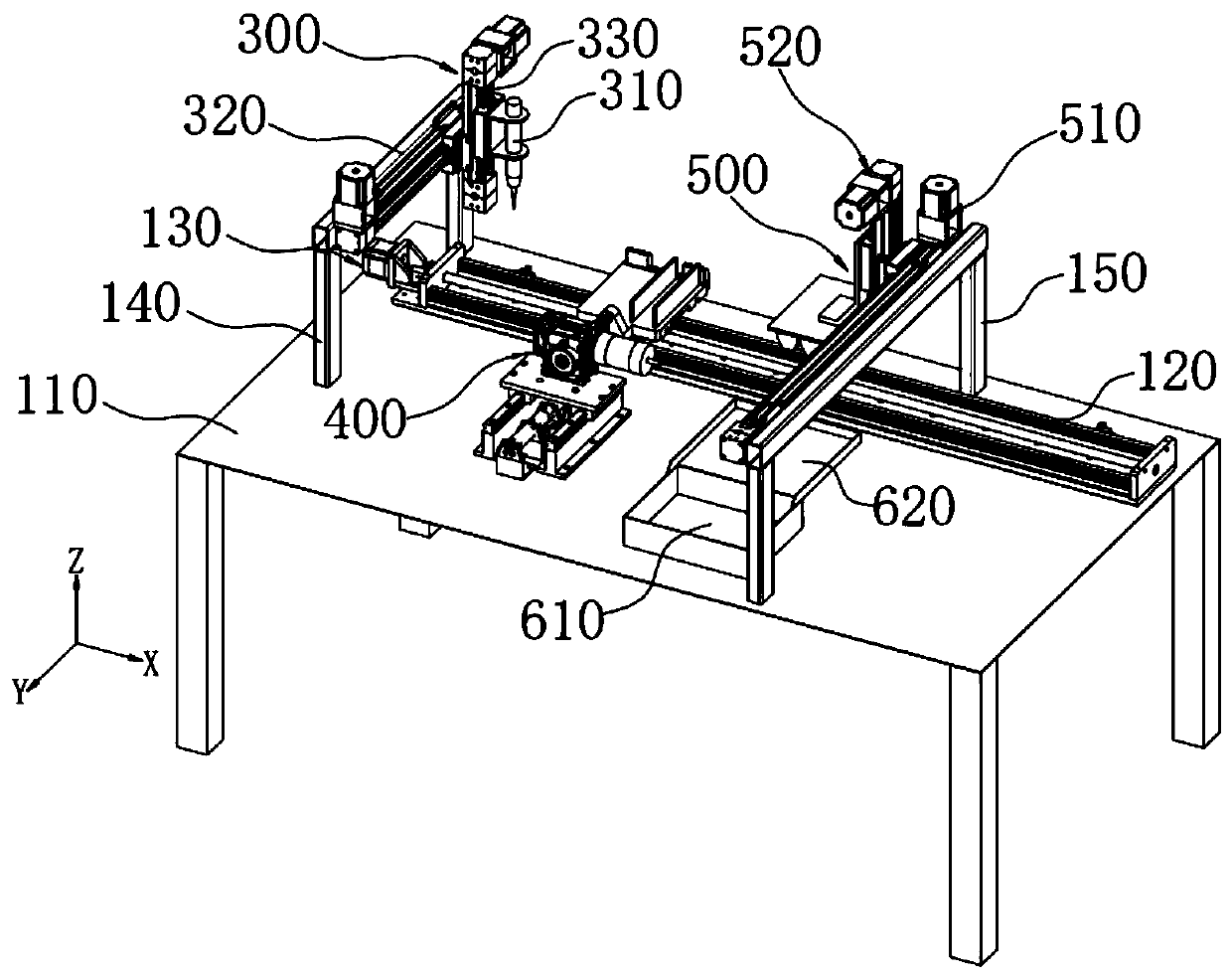
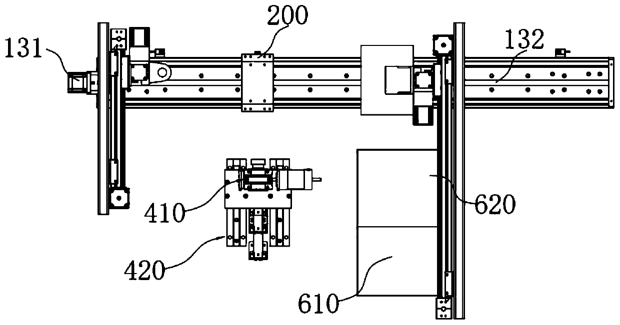
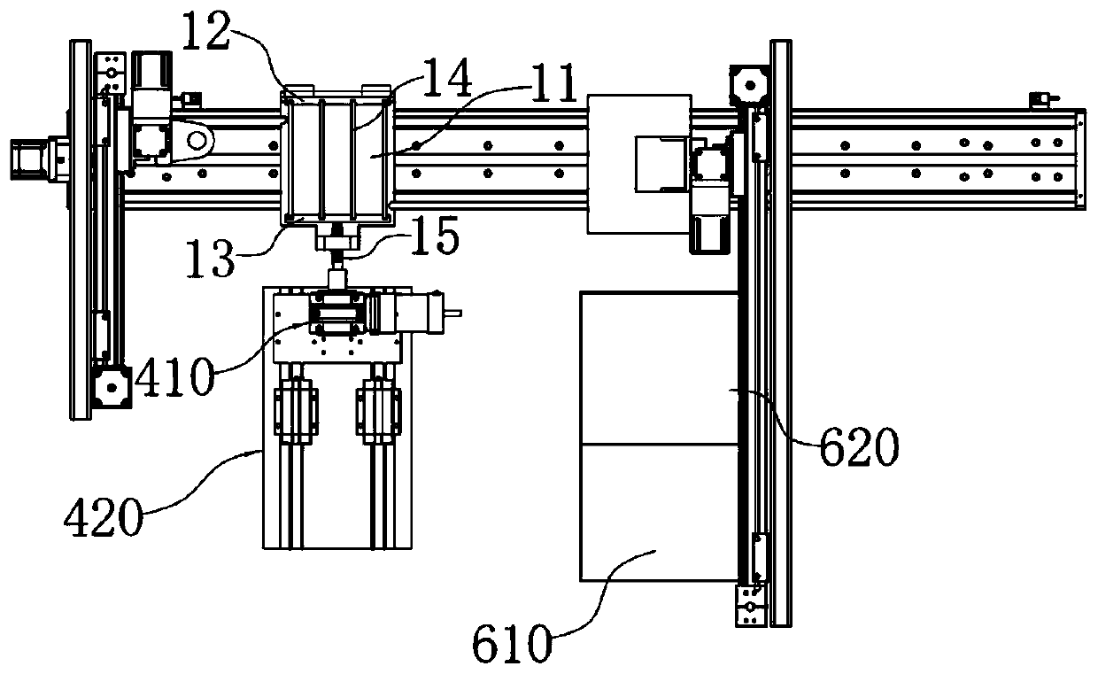
The invention provides a test mold assembly device, and relates to the technical field of assembly machines. The test mold assembly device comprises a work table, an assembly table, an oil injection module and a jacking mechanism, wherein the assembly table is mounted on the work table, and a test mold part is fed to the assembly table through a feeding mechanism; the oil injection module comprises an injection gun used for spraying sealing oil and a first moving module which drives the injection gun to move and can enable a gun opening of the injection gun to face a test mold base on the assembly table, and the first moving module is mounted on the work table. The jacking mechanism comprises a revolving drive assembly and a first driving mechanism which drives the revolving drive assemblyto do linear motion. The technical problems in the prior art are solved that a test mold is assembled totally depending on manual work, the working intensity of operators is high, and the efficiencyis low.

Description

technical field [0001] The invention relates to the technical field of assembly machinery, in particular to a trial mold assembly equipment. Background technique [0002] The cement mortar test mold is a special tool for forming cement strength test blocks. In the prior art, the trial mold is mainly composed of a trial mold base, an upper baffle, a lower baffle, and a plurality of partitions connected between the upper baffle and the lower baffle. Wherein, the trial mold base, the upper baffle plate, the lower baffle plate and the plurality of partitions jointly form a plurality of trial mold grooves, and the number of the trial mold grooves is 1 less than the number of the partition plates. In addition, there are trial bolts threaded on the lower baffle, and the rotation of the trial bolt can drive the lower baffle closer to or away from the upper baffle; in simple terms, when the lower baffle moves close to the upper baffle, the partition is clamped to the upper between ...

Claims


Application Information

Patent Timeline
Patent Type & Authority Applications(China)
IPC IPC(8): B23P21/00B05B13/02B05C7/06B05C11/10
CPCB05B13/0221B05C7/06B05C11/1039B23P19/001B23P21/00
Inventor 刘正权王枫尹德海艾富强于吉苏
Owner NANJING SINOTEST ROBOTICS CO LTD
Why Eureka
Try Eureka