An automatic detection device for the discharge voltage of an engine ignition nozzle

An automatic detection device and discharge voltage technology, applied in the direction of engine ignition, measuring devices, engine components, etc., can solve problems such as complex operation process, large data deviation, human factor interference, etc., achieve high detection accuracy, eliminate data deviation, and accuracy high effect

Active Publication Date: 2021-08-13
四川泛华航空仪表电器有限公司
View PDF0 Cites 0 Cited by
  • Summary
  • Abstract
  • Description
  • Claims
  • Application Information

AI Technical Summary

Problems solved by technology

Its shortcomings are: the operation process is complicated, human factors are introduced, and the data deviation is relatively large due to the return error caused by the mechanical knob

Method used


Image

  • An automatic detection device for the discharge voltage of an engine ignition nozzle
  • An automatic detection device for the discharge voltage of an engine ignition nozzle

Examples


Embodiment 1

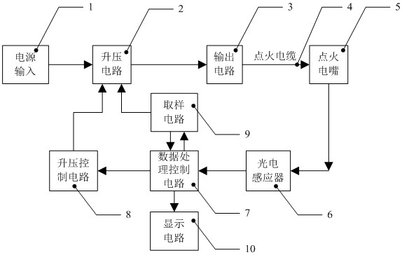
[0020] An automatic detection device for the discharge voltage of an engine ignition nozzle, comprising a boost circuit 2, a boost control circuit 8, a data processing control circuit 7, a photoelectric sensor 6, a sampling circuit 9, and an ignition nozzle 5; the boost circuit 2 The boost control circuit 8 and the sampling circuit 9 are respectively connected, the ignition nozzle 5 is respectively connected to the boost circuit 2 and the photoelectric sensor 6, and the data processing control circuit 7 is respectively connected to the boost control circuit 8, the sampling circuit 9, the photoelectric Inductor 6; the boost control circuit 8 is used to control the voltage rise and fall of the boost circuit 2, the sampling circuit 9 is used to monitor the voltage value of the boost circuit 2, and the photoelectric sensor 6 is used for sensing points Whether there is a discharge spark at the thermal nozzle 5.

[0021] During the use of the present invention, the voltage value of ...

Embodiment 2

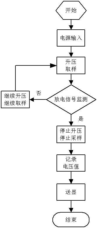
[0026] An automatic detection device for the discharge voltage of an engine ignition nozzle, such as figure 1 , figure 2 As shown, it can be used to detect the discharge voltage of the ignition nozzle 5; it includes a booster circuit 2 including a digital control transformer, an output circuit 3, a photoelectric sensor 6 for detecting the discharge state of the ignition nozzle 5, and the voltage of the booster circuit 2 The sampling circuit 9 for monitoring the value, the boost control circuit 8 for controlling the voltage value of the boost circuit 2, the data processing control circuit 7 and the display circuit 10 for displaying the discharge voltage value of the ignition nozzle 5.

[0027] Whether the voltage of the boost circuit 2 rises is controlled by the boost control circuit 8, and the working state of the boost control circuit 8 depends on whether the photoelectric sensor 6 senses the discharge spark of the ignition nozzle 5; The voltage value of the voltage circuit...


PUM


Abstract

The invention discloses an automatic detection device for the discharge voltage of an engine ignition nozzle, comprising a boost circuit, a boost control circuit, a data processing control circuit, a photoelectric sensor, a sampling circuit, and an ignition nozzle; A voltage control circuit and a sampling circuit, the ignition nozzle is respectively connected to a boost circuit and a photoelectric sensor, and the data processing control circuit is respectively connected to a boost control circuit, a sampling circuit, and a photoelectric sensor; the boost control circuit is used for Controlling the voltage rise and fall of the boost circuit, the sampling circuit is used to monitor the voltage value of the boost circuit, and the photoelectric sensor is used to sense whether there is a discharge spark in the ignition nozzle. The invention realizes the automatic detection of the discharge voltage of the ignition nozzle of the engine, which is more convenient and concise than the complex operation process of pre-estimation and knob adjustment in the traditional technology.

Description

technical field [0001] The invention belongs to the technical field of an engine ignition nozzle detection device, in particular to an engine ignition nozzle discharge voltage automatic detection device. Background technique [0002] The aircraft engine is the heart of the aircraft, and the aviation ignition system is one of the important components of the aircraft engine. As an important component of the ignition system, the ignition nozzle is an important component of the ignition system, and its performance directly affects the reliability and safety of the engine. The discharge voltage of the ignition nozzle of the engine is an important parameter to test its performance. The discharge voltage of the ignition nozzle refers to the minimum input voltage that breaks down the ignition nozzle to generate a discharge spark. [0003] At present, the detection of the discharge voltage of the ignition nozzle of aerospace engines still uses a mechanical knob type autotransformer t...

Claims


Application Information

Patent Timeline
Patent Type & Authority Patents(China)
IPC IPC(8): F02P17/12F02P5/145G01R19/00
CPCF02P5/145F02P17/12F02P2017/121G01R19/0084
Inventor 袁札杨辉达会平朱书乔杨荻
Owner 四川泛华航空仪表电器有限公司
Why Eureka
Try Eureka