Fuel gas adjusting valve

A technology for gas regulation and intake valves, which is applied in the direction of multi-way valves, valve devices, engine components, etc., and can solve problems that affect safety, fail to solve the problem of stepping motor valve flow hysteresis, and the first valve core is not tightly sealed. , to achieve the effect of high security

Active Publication Date: 2020-06-02
NINGBO FOTILE KITCHEN WARE CO LTD
View PDF22 Cites 2 Cited by
  • Summary
  • Abstract
  • Description
  • Claims
  • Application Information

AI Technical Summary

Problems solved by technology

[0005] First, due to the hard connection between the first valve stem and the first valve core, the first valve rod drives the first valve core to move excessively to the left to achieve sealing; this will greatly damage the first valve core, A long time will affect the security
[0006] Second, if the output shaft of the driving device loses steps during the leftward movement (the first spool should move to the left, but actually the first spool does not move to the left), it will also cause the first spool to move to the left. The seal is not tight, and it is easy to leak air
[0007] Third, through the cooperation of the first valve stem and the first valve core, the adjustment accuracy is relatively low, which cannot well meet the accuracy requirements for the low fire adjustment of the gas stove
[0008] Fourth, the problem of large flow hysteresis of stepper motor valves (valve driven by stepper motors) is not solved

Method used


Image

  • Fuel gas adjusting valve
  • Fuel gas adjusting valve
  • Fuel gas adjusting valve

Examples


Embodiment Construction

[0021] The present invention will be further described in detail below in conjunction with the accompanying drawings and embodiments.

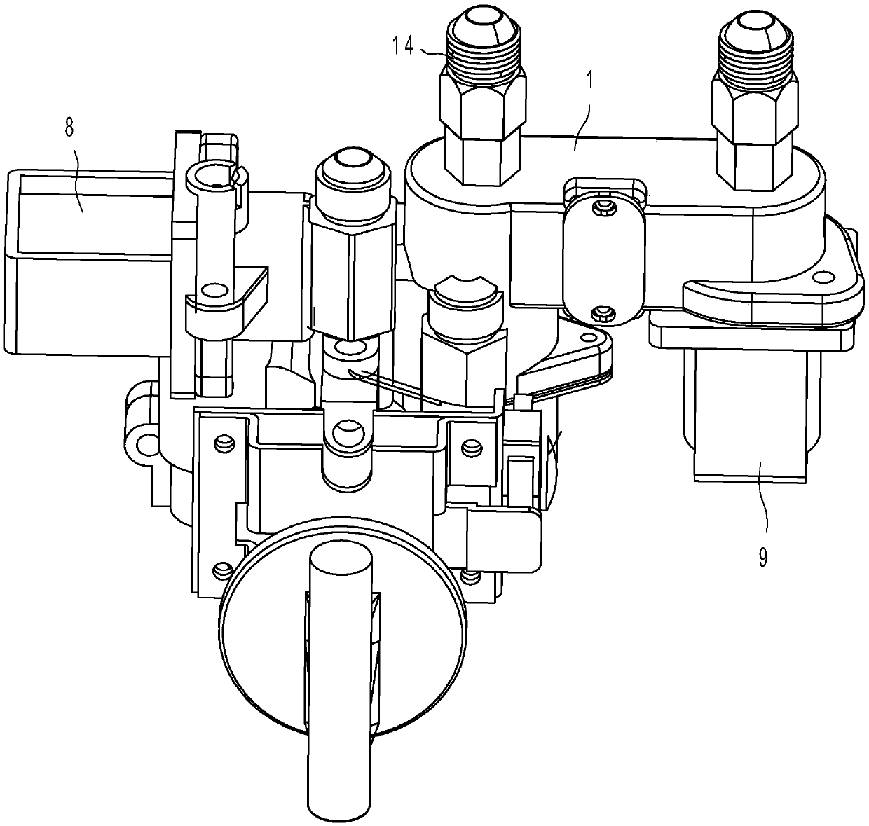
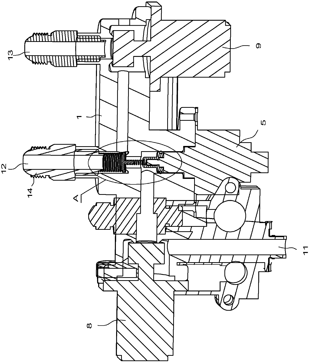
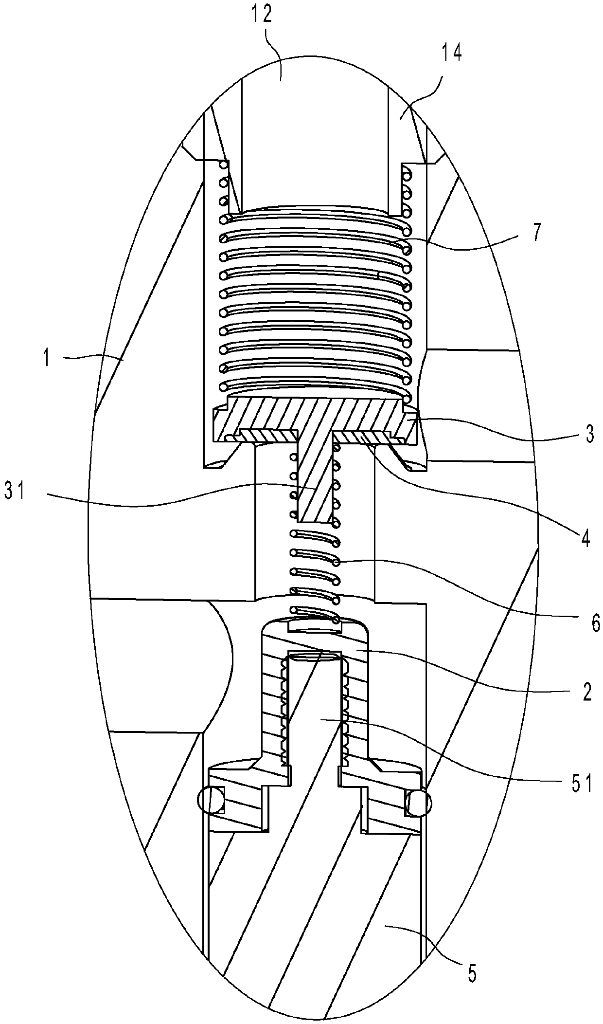
[0022] Such as Figure 1 ~ Figure 3 As shown, the gas regulating valve includes a valve body 1, a valve stem 2, a valve core 3 and a driving device 5. The air channel 11, the inner ring air outlet channel 12 and the outer ring air outlet channel 13 can all communicate with the valve cavity and the outside world; The flow rate of the inner ring outlet channel 12 and the outer ring outlet channel 13; the driving device 5 is provided with an output shaft 51, the output shaft 51 is connected with the valve stem 2 to drive the valve core 3 to move axially in the valve cavity, and the gas control valve also includes The first compression spring 6 and the second compression spring 7 both located in the valve chamber of the valve body 1, one end of the first compression spring 6 is against the lower end of the valve core 3, and the other end of the f...


PUM


Abstract

A fuel gas adjusting valve comprises a valve body, a valve rod, a valve element and a driving device; the valve body is provided with a valve cavity, an air inlet channel, an inner ring air outlet channel and an outer ring air outlet channel; the valve rod is in linkage in valve element, and the valve element is movably arranged in the valve cavity of the valve body and can adjust the flow rate ofthe inner ring air outlet channel and the flow rate of the outer ring air outlet channel; and the driving device is provided with an output shaft, and the output shaft is connected with the valve rodto drive the valve element to move in the valve cavity in the axial direction. The fuel gas adjusting valve further comprises a first compression spring and a second compression spring, and the elastic coefficient of the second compression spring is larger than that of the first compression spring. By arranging the first compression spring, the valve rod is in flexible connection with the valve element, compared with the mode that a valve element is extruded to be sealed through the excessive stroke of an output shaft of the driving mechanism in the prior art, according to the fuel gas adjusting valve, through action of the first compression spring and the second compression spring, sealing is formed, damage of the first compression spring to the valve element is small, accordingly, the situation that sealing is influenced due to the fact that the valve element is damaged is avoided, and the safety is high.

Description

technical field [0001] The invention relates to the technical field of gas flow control, in particular to a gas regulating valve. Background technique [0002] Intelligent control of gas stoves is a major trend in the research of modern kitchen appliances. On the one hand, how to achieve precise and stable firepower control of gas stoves is an important direction of gas stove research. On the other hand, with the improvement of people's requirements for kitchen space utilization, the built-in, flat and ultra-thin concept cooker also puts forward higher requirements for the gas valve body system. [0003] Existing gas cookers are provided with electric control valves, mainly stepping motor-driven cock valves, such as the Chinese utility model patent "A Kind of Gas Intelligent Control of Gas Cookers" whose patent number is ZL201220184529. valve". In addition, there are proportional valves with membranes, such as the Chinese utility model patent "Gas Stove" with patent numbe...

Claims


Application Information

Patent Timeline
IPC IPC(8): F16K11/22
CPCF16K11/22
Inventor 钟健郑军妹俞瑜严力峰
Owner NINGBO FOTILE KITCHEN WARE CO LTD
Why Eureka
Try Eureka