Underwater pipeline detection device based on fiber laser

A technology for fiber lasers and underwater pipelines, applied in measuring devices, fluid pressure measurement using optical methods, pipeline systems, etc., can solve problems such as reduced service life, low operating costs, and environmental pollution, so as to improve service life and prevent The effect of pipe damage and easy operation

Inactive Publication Date: 2020-06-02
苏州高新区建金建智能科技有限公司
View PDF0 Cites 3 Cited by
  • Summary
  • Abstract
  • Description
  • Claims
  • Application Information

AI Technical Summary

Problems solved by technology

[0002] Underwater oil and natural gas pipelines continuously transport a large amount of oil and natural gas on the seabed through closed pipelines. It is an important part of the development and production system of offshore oil and gas fields, and it is also the fastest, safest, most economical and reliable way of offshore oil and gas transportation. , with high oil and gas transportation efficiency, large oil transportation capacity, convenient management and low operating costs, but underwater oil and natural gas pipelines are located on the seabed, and most of the pipelines need to be buried in the soil at a certain depth on the seabed, so it is impossible to detect pipelines in real time When detecting pipelines, ordinary sensors will fail or be damaged due to the influence of the surrounding environment of the pipeline, which will reduce their service life, make it inconvenient to maintain the sensor, and need to supply power to the sensor separately. The soil will be affected by seawater and will decrease over time, which will cause accidental damage to pipelines, oil and gas leakage, and pollute the environment

Method used


Image

  • Underwater pipeline detection device based on fiber laser
  • Underwater pipeline detection device based on fiber laser
  • Underwater pipeline detection device based on fiber laser

Examples


Embodiment approach

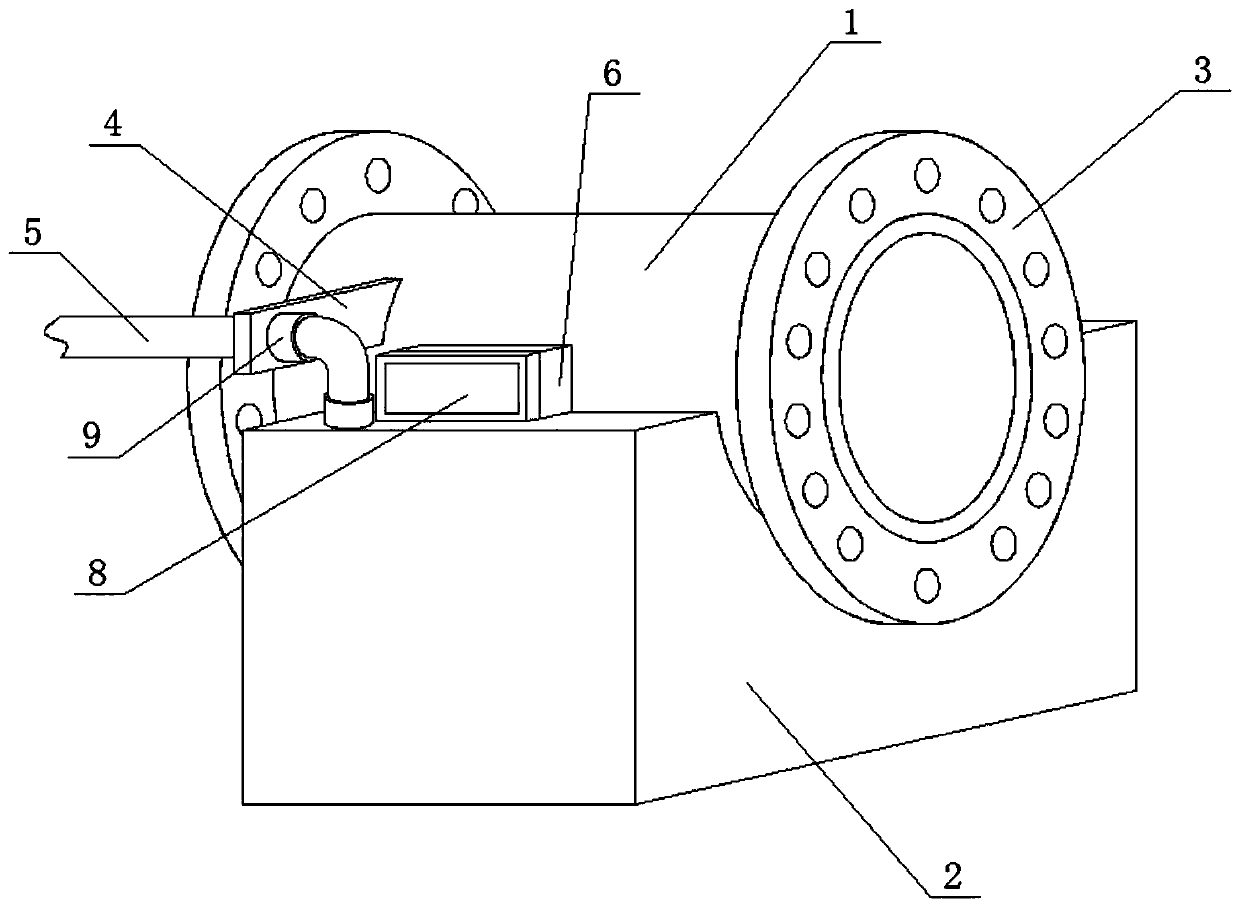
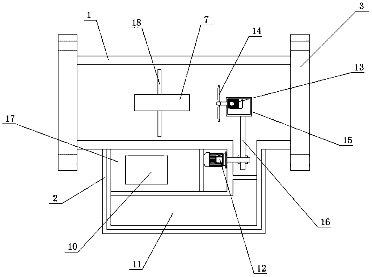
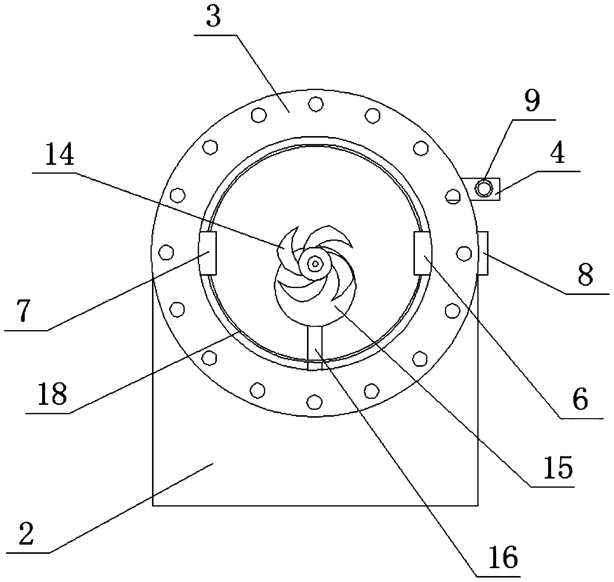
[0027] As a preferred embodiment of the present invention, the controller 10 is connected with battery one 11, battery two 12, stepping motor 12, small generator 13 and modulator 19 through wires, and the control box 10 is connected with optical fiber through wires. The transmitter 7, the optical fiber receiver 6 and the optical fiber sensor 8 are connected, and the modulator 19 is connected with the monitoring center through the optical fiber 18, and can detect changes in the environment inside and outside the pipeline in real time.

[0028] As a preferred embodiment of the present invention, the controller 10 includes a control board and a control switch 23, and a microprocessor 22 is mounted on the control board.

[0029] As a preferred embodiment of the present invention, the control system includes an optical fiber receiver 6, an optical fiber transmitter 7, an optical fiber sensor 8, a controller 10, a battery one 11, a battery two 21, a stepping motor 12, and a small gen...


PUM


Abstract

The invention provides an underwater pipeline detection device based on a fiber laser. The underwater pipeline detection device comprises a body and a control system, flanges are symmetrically arranged on the two sides of the body, and through holes are formed in the flanges. A storage box is fixedly installed at the bottom of the body, a fiber optic receiver and a fiber optic emitter are symmetrically installed on the two sides of the top of the storage box, a fiber optic sensor is fixedly installed on one side of the fiber optic receiver, and a fiber optic is fixedly installed between the fiber optic emitter and the fiber optic receiver. According to the underwater pipeline detection device based on the fiber laser, the service life of a small engine is prolonged, data detected for multiple times are compared, whether oil and gas leakage happening to a certain segment of a pipeline or not can be determined, the operation is simple and convenient, the positioning is accurate, and through the fiber optic sensor outside the body, the situation that the pipeline is damaged due to reduced soil on the periphery of the pipeline and the environment is polluted due to the oil and gas leakage is prevented.

Description

technical field [0001] The invention relates to the technical field of pipeline detection, in particular to an underwater pipeline detection device based on a fiber laser. Background technique [0002] Underwater oil and natural gas pipelines continuously transport a large amount of oil and natural gas on the seabed through closed pipelines. It is an important part of the development and production system of offshore oil and gas fields, and it is also the fastest, safest, most economical and reliable way of offshore oil and gas transportation. , with high oil and gas transportation efficiency, large oil transportation capacity, convenient management and low operating costs, but underwater oil and natural gas pipelines are located on the seabed, and most of the pipelines need to be buried in the soil at a certain depth on the seabed, so it is impossible to detect pipelines in real time When detecting pipelines, ordinary sensors will fail or be damaged due to the influence of ...

Claims


Application Information

Patent Timeline
Patent Type & Authority Applications(China)
IPC IPC(8): F17D5/06G01K11/32G01L11/02
CPCF17D5/06G01K11/32G01L11/02
Inventor 林建斌
Owner 苏州高新区建金建智能科技有限公司
Why Eureka
Try Eureka