
Vertical orthodontic anchorage nail maximum bearing torque measuring device and using method

A technology of torque measurement and orthodontics, which is applied in the field of vertical orthodontic anchorage nails to withstand the maximum torque measurement device, can solve the problems of measurement accuracy, radial deviation of weight, and small volume of orthodontic anchorage nails, etc., to improve The effects of measurement accuracy, prevention of axial displacement, and easy disassembly and assembly

Active Publication Date: 2020-06-02
HARBIN UNIV OF SCI & TECH
View PDF13 Cites 0 Cited by
  • Summary
  • Abstract
  • Description
  • Claims
  • Application Information

AI Technical Summary

Problems solved by technology

Most of the torque tests are carried out with the help of a digital torsion meter. During the test, the digital torsion meter is held by human hands, which makes it difficult to guarantee the stability, and it is difficult to clamp the orthodontic anchorage nails. The end types and sizes of the orthodontic anchorage nails are various. , especially the orthodontic anchorage nails with triangular ends are more difficult to clamp
[0004] There are many horizontal torque measuring devices, which are suitable for use under the conditions of high rigidity and high torque of the measured object, while the orthodontic anchorage nail is small in size and light in weight. If a horizontal torque measuring device is used for measurement, the weight of the measuring device itself Radial deviation will occur, which will have a great impact on measurement accuracy

Method used


Image

  • Vertical orthodontic anchorage nail maximum bearing torque measuring device and using method
  • Vertical orthodontic anchorage nail maximum bearing torque measuring device and using method
  • Vertical orthodontic anchorage nail maximum bearing torque measuring device and using method

Examples


Embodiment Construction

[0025] In order to make the object, technical solution and advantages of the present invention clearer, the present invention is described below through specific embodiments shown in the accompanying drawings. It should be understood, however, that these descriptions are exemplary only and are not intended to limit the scope of the present invention. Also, in the following description, descriptions of well-known structures and techniques are omitted to avoid unnecessarily obscuring the concept of the present invention.

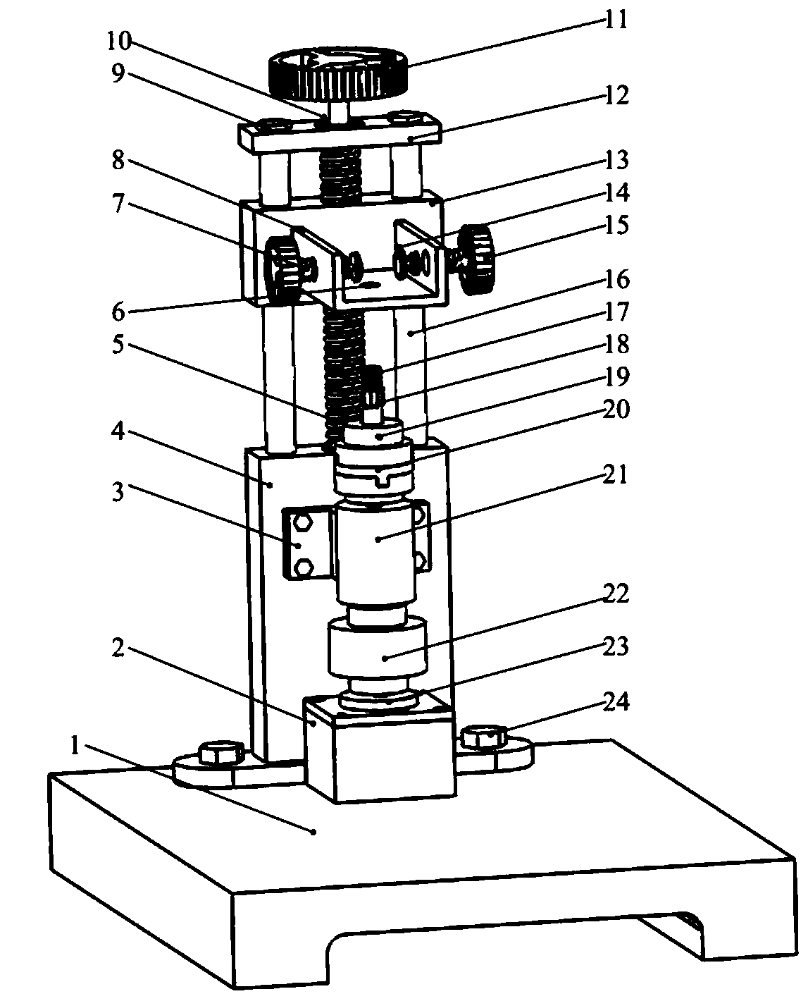
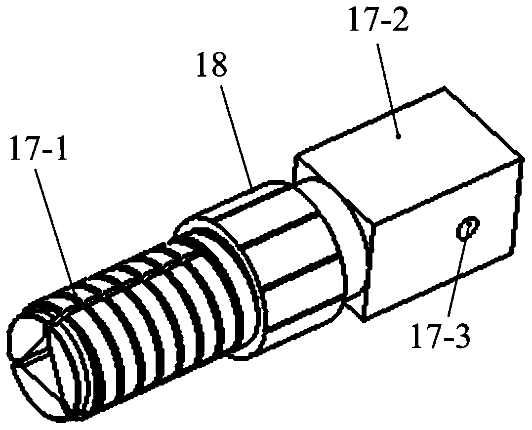
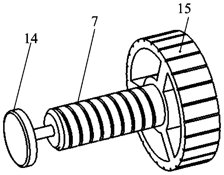
[0026] Such as figure 1 , figure 2 , image 3 , Figure 4 , Figure 5As shown, the specific embodiment of the present invention adopts the following technical solutions: a vertical orthodontic anchorage nail maximum bearing torque measuring device and using method, which includes a base 1, a motor base 2, a sensor support 3, a support plate 4, a wire Bar 5, Anchorage Nail Positioning Hole 6, Clamping Bolt 7, Simulated Jawbone Tissue Support Table 8, Set ...


PUM


Abstract

The invention discloses a vertical orthodontic anchorage nail maximum bearing torque measuring device and a using method, and relates to the field of orthodontic measuring tools. A support plate is connected with a base; a stepping motor is mounted on a motor base of the base; a first coupling is connected with a rotating shaft of the stepping motor; a torque sensor is fixedly connected to the support plate and installed at the upper end of the first coupling; an embeddable cross slider coupling is mounted at the upper end of the torque sensor; an anchorage nail clamping column is embedded into the embeddable cross slider coupling and is fixed to the embeddable cross slider coupling through a clamping column fixing pin; a screwing nut and a threaded part of the anchorage nail clamping column are installed in a matched mode; a simulated jaw tissue supporting table is installed on a lead screw and two cylindrical guide rails, height adjustment is conducted by rotating the lead screw; andclamping bolts are installed on the two sides of the simulated jaw tissue supporting table. The device can quickly and accurately measure the maximum bearing torque of an orthodontic anchorage nail,and has the advantages of compact structure, small error and the like.

Description

technical field [0001] The invention relates to a vertical orthodontic anchorage screw bearing maximum torque measuring device and a use method, belonging to the technical field of oral orthodontic measuring tools. Background technique [0002] Anchorage control has always been the focus of orthodontic treatment. As a temporary anchorage device, orthodontic anchorage nails can provide orthodontic orthodontic force during orthodontic treatment. Stable anchorage is the decisive factor. The basis for treatment planning and achieving good treatment outcomes. The orthodontic anchorage screw obtains good initial stability by forming a good mechanical lock between the thread and the implanted bone tissue, and can immediately load the orthodontic force. [0003] Scholars at home and abroad have conducted extensive research and a large number of tests on the initial stability and immediate load capacity of orthodontic anchorage screws, including torque tests and pull-out tests. Mos...

Claims


Application Information

Patent Timeline
Patent Type & Authority Applications(China)
IPC IPC(8): G01M13/00
CPCG01M13/00
Inventor 姜金刚王磊左晖曾阳张永德梁瑞奇
Owner HARBIN UNIV OF SCI & TECH
Learn More