Large cable-strut truss type deployable antenna mechanism

A truss-type, cable-rod technology, which is applied to antennas, folded antennas, rotating antennas and other directions suitable for movable objects, can solve the problems of low rigidity and large quality of the cable-rod mechanism, and achieves light weight, mature processing technology, Stable and reliable work

Active Publication Date: 2020-06-02
TAIYUAN UNIV OF TECH
View PDF9 Cites 4 Cited by
  • Summary
  • Abstract
  • Description
  • Claims
  • Application Information

AI Technical Summary

Problems solved by technology

[0005] In order to solve the problems of large mass and low rigidity of the existing cable-strut mechanism, the present invention further provides a large-scale cable-strut truss type deployable antenna mechanism; this mechanism has the advantages of light weight, high rigidity, and large folding-to-expansion ratio. And it can realize unfolding according to the elastic potential energy stored in its own deformation.

Method used


Image

  • Large cable-strut truss type deployable antenna mechanism
  • Large cable-strut truss type deployable antenna mechanism
  • Large cable-strut truss type deployable antenna mechanism

Examples


Embodiment Construction

[0028] The present invention is described in detail below in conjunction with accompanying drawing:

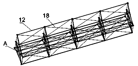
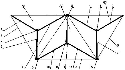
[0029] Such as figure 1 As shown, a large-scale cable-truss-type deployable antenna mechanism includes five cable-truss-type deployable units A, and the five deployable units A are connected by connecting longitudinal rods 12 to form a cable-truss-type deployable antenna mechanism. Expanding the antenna mechanism; the expandable unit A includes two first expandable components A1 and a second expandable component A2 arranged between the first expandable components A1, the first expandable component A1 and the The second expandable component A2 is a tripod body, and the first expandable component A1 and the second expandable component A2 are connected by a third torsion spring joint 5 to form the expandable unit A.

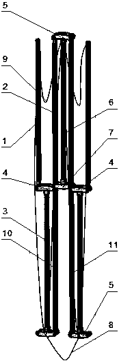
[0030] Such as figure 2 , image 3 As shown, the first expandable component A1 includes a first slant bar 1, a second slant bar 2, a first vertical bar 3, and a...


PUM


Abstract

The invention belongs to the technical field of aerospace appliances and equipment, and particularly relates to a large cable-strut truss type deployable antenna mechanism. The cable-strut truss typedeployable antenna mechanism comprises a plurality of cable-strut truss type deployable units, wherein the plurality of deployable units are connected through connecting longitudinal rods to form thecable-strut truss type deployable antenna mechanism; each deployable unit comprises first deployable assemblies and a second deployable assembly arranged between the first deployable assemblies, the first deployable assemblies and the second deployable assemblies are triangular support bodies, and the first deployable assemblies and the second deployable assemblies are connected through third torsion spring connectors to form the deployable units. The large cable-strut truss type deployable antenna mechanism is good in reliability, compact in structure, good in rigidity after being completelyunfolded, capable of meeting the use requirement of a large space antenna and suitable for a satellite space folding and unfolding mechanism and the like.

Description

technical field [0001] The invention belongs to the technical field of aerospace equipment and equipment, and in particular relates to a large-scale cable rod truss type deployable antenna mechanism. Background technique [0002] In the aerospace structure, the deployable truss mechanism is a kind of space deployable mechanism. The mechanism can be deployed into a three-dimensional truss mechanism through the extension of the rods. The ability to expand on rails or expand in space. [0003] Compared with the deployable structure in the form of simple rods, the deployable mechanism in the form of cables has a smaller mass. The expanded shape of the expandable mechanism is generally its working state. To maintain the unfolded state for a long time, most deployable structures are locked by adding locking devices or other components; moreover, the mechanism also needs the rods to move synchronously during the process of unfolding or folding, which requires the addition of gear...

Claims


Application Information

Patent Timeline
Patent Type & Authority Applications(China)
IPC IPC(8): H01Q1/08H01Q1/28
CPCH01Q1/08H01Q1/084H01Q1/28
Inventor 张静王雪妮寇子明李盘浩
Owner TAIYUAN UNIV OF TECH
Why Eureka
Try Eureka