
A Node Interlocking Protection Method Applicable to Multiple Power Supply Modes

An interlocking protection, node technology, applied in the direction of emergency protection circuit devices, electrical components, etc., can solve the problem of no systematic solution, and achieve the effect of reducing the difficulty

Active Publication Date: 2022-02-15
NARI TECH CO LTD +1
View PDF7 Cites 1 Cited by
  • Summary
  • Abstract
  • Description
  • Claims
  • Application Information

AI Technical Summary

Problems solved by technology

[0010] For the above-mentioned multi-power supply situations, there is currently no systematic solution, which brings new challenges to primary system design, functional design and setting of relay protection

Method used


Image

  • A Node Interlocking Protection Method Applicable to Multiple Power Supply Modes
  • A Node Interlocking Protection Method Applicable to Multiple Power Supply Modes
  • A Node Interlocking Protection Method Applicable to Multiple Power Supply Modes

Examples


Embodiment Construction

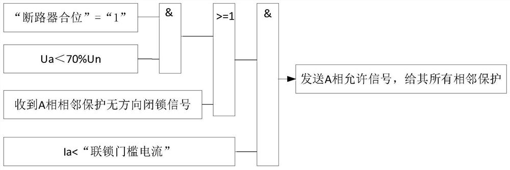
[0077] Attached below Figure 10 The AC medium-voltage power supply system for urban rail transit specifically analyzes and explains in detail the various protection action behaviors of the present invention at various fault points under various power supply modes.

[0078] It is assumed here that the longitudinal difference protection of the optical fiber at both ends of the line between the two stations is not working or not set.

[0079] 1. Line L BC1 A fault occurs at point k1 in the middle (line fault)

[0080] 1) When there is only single power supply 1

[0081] DL1(C1) fault phase has low voltage and no flow, does not send blocking signal, and sends permission signal to all its adjacent protection DL2(B1), DL2(C1).

[0082] The fault phase current of DL2 (B1) is greater than the "non-directional blocking trip current", and the line L connected to it has not been received. BC1 The non-directional blocking signal sent by the only adjacent protection DL1 (C1) of the no...


PUM


Abstract

The invention discloses a node interlocking protection method suitable for multiple power supply modes. The method uses the node theory to define the adjacent protection of each node. It stipulates the positive direction of various protections, determines the forward and reverse direction of the current through the judgment of the positive direction, and proposes the permissive protection and reverse blocking protection, which overcomes the problem of non-directional blocking protection in multi-power supply systems. It is suitable for Various power supply methods only need to interlock the protection of the station and the protection of the incoming and outgoing lines entering and leaving the station to realize the interlocking protection of the entire power grid, which reduces the difficulty of method implementation and maintenance. If the optical fiber differential protection between lines does not work or is not set, it can still provide complete protection against failures in various power supply modes. When the GOOSE network is used to transmit the interlocking signal mode, in the GOOSE switch, the network grouping can be carried out according to one station, which avoids the network abnormal message that may be caused by the whole line one network method and spreads to the whole line.

Description

technical field [0001] The invention relates to a relay protection method for node interlocking, which belongs to the field of protection control. Background technique [0002] In the ring network power supply system, such as the AC medium voltage power supply system of urban rail transit, the longitudinal difference of optical fiber is usually set between the two stations as the main protection, and the definite time overcurrent protection is set as the backup protection according to the ladder principle. The combination of the two constitutes Complete protection. Due to the requirements of the maximum allowable time limit for the main substation that supplies power to urban rail transit, the number of definite-time overcurrent protection stages set according to the ladder principle cannot be too many to ensure that the time limit will not exceed the requirements of the main substation. [0003] Relay protection manufacturers have adopted some methods, typically sending bl...

Claims


Application Information

Patent Timeline
Patent Type & Authority Patents(China)
IPC IPC(8): H02H7/26H02H7/28H02H7/22
CPCH02H7/26H02H7/28H02H7/261H02H7/22
Inventor 李钢吴永文朱微维
Owner NARI TECH CO LTD
Learn More