
Flow monitoring method and device applied to power collection system

A technology for power collection and flow monitoring, applied in transmission systems, electrical components, etc., can solve problems such as inability to systematically monitor flow, inconvenient management of the monitoring master station, and achieve the effect of improving management efficiency

Active Publication Date: 2022-03-29
BEIJING SMARTCHIP MICROELECTRONICS TECH COMPANY +3
View PDF0 Cites 0 Cited by
  • Summary
  • Abstract
  • Description
  • Claims
  • Application Information

AI Technical Summary

Problems solved by technology

[0003] Since the collection terminal and the monitoring master station are connected through a cellular network, for example, through a GPRS or LTE (LongTerm Evolution, long-term evolution) network connection, the current data transmission flow of the power collection system is managed by the network operator, and the monitoring The master station can only query the system traffic through the network operator, but cannot directly monitor the system traffic, which makes the management of the monitoring master station inconvenient

Method used


Image

  • Flow monitoring method and device applied to power collection system
  • Flow monitoring method and device applied to power collection system
  • Flow monitoring method and device applied to power collection system

Examples


Embodiment Construction

[0040] The specific implementation manners of the embodiments of the present invention will be described in detail below in conjunction with the accompanying drawings. It should be understood that the specific implementation manners described here are only used to illustrate and explain the embodiments of the present invention, and are not intended to limit the embodiments of the present invention.

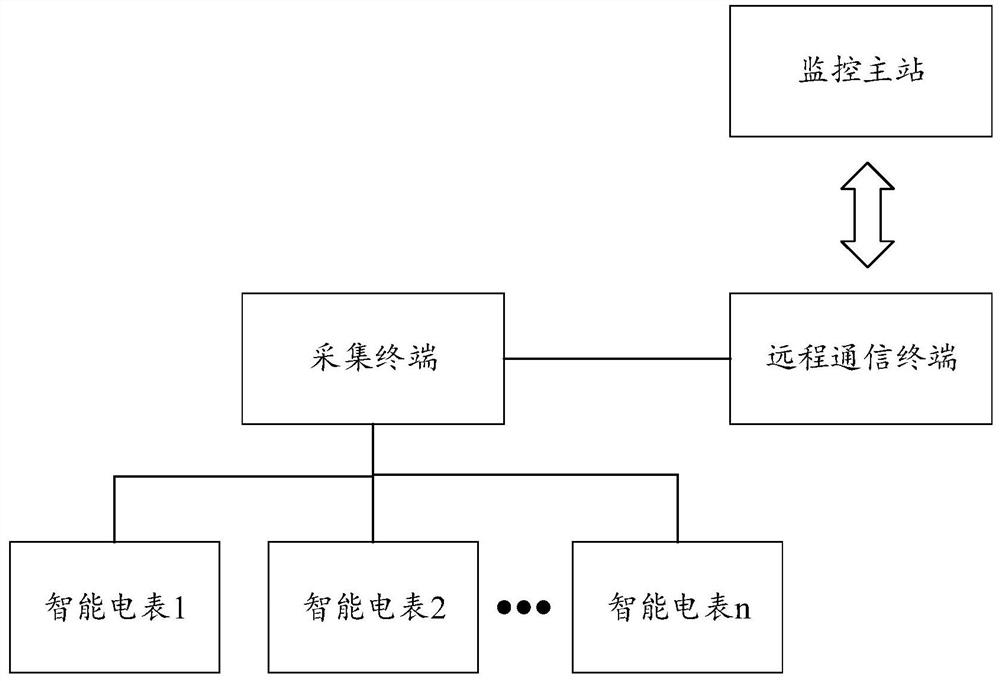
[0041] Such as image 3 As shown, the existing power collection system includes: a collection terminal, a remote communication terminal and a monitoring master station, and the collection terminal is connected to the monitoring master station through the remote communication terminal. Among them, the collection terminal is used to collect the electricity consumption information of the user, and the electricity consumption information is usually meter data, and one collection terminal can be connected with hundreds or more smart meters to collect the electricity consumption informa...


PUM


Abstract

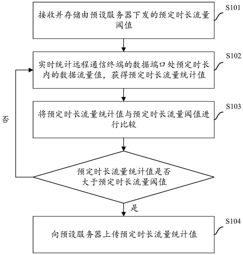
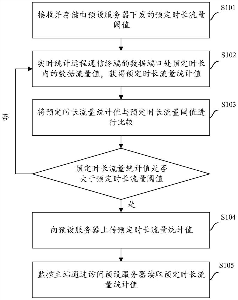
The invention relates to the technical field of data flow monitoring, and provides a flow monitoring method applied to a power collection system. The power collection system includes a collection terminal, a remote communication terminal and a monitoring master station. The method is executed at the remote communication terminal. The method Including: 1) receiving and storing the scheduled time flow threshold issued by the preset server; 2) real-time statistics of the data flow value within the predetermined time at the data port of the remote communication terminal to obtain the predetermined time flow statistics; 3) the predetermined time The traffic statistics value is compared with the predetermined duration traffic threshold, if the comparison result is that the predetermined duration traffic statistics value is greater than the predetermined duration traffic threshold, then perform step 4), otherwise return to step 2); 4) upload the predetermined duration traffic statistics value to the preset server . The technical solution provided by the invention can directly monitor the flow of the power collection system, thereby improving the management efficiency of the power collection system.

Description

technical field [0001] The invention relates to the technical field of data flow monitoring, in particular to a flow monitoring method applied to a power collection system and a flow monitoring device applied to a power collection system. Background technique [0002] At present, wireless communication technology has been widely used in the power industry. The power collection system uses the existing cellular network resources, so that the monitoring master station in the system and the collection terminal are connected through wireless communication. Among them, the collection terminal is used to collect the user's electricity consumption information (usually electricity meter data), and the collected electricity consumption information is sent to the monitoring master station through the above-mentioned cellular network, and the monitoring master station performs electricity consumption statistics and electricity consumption statistics for the user. manage. [0003] Sin...

Claims


Application Information

Patent Timeline
Patent Type & Authority Patents(China)
IPC IPC(8): H04L43/0876H04L43/04H04L43/16
CPCH04L43/0876H04L43/04H04L43/16
Inventor 唐晓柯崔炳荣孙鹏甘杰
Owner BEIJING SMARTCHIP MICROELECTRONICS TECH COMPANY
Learn More