
Nursing sputum suction device for respiratory department

A suction tube and support plate technology, used in suction containers, suction devices, hypodermic injection devices, etc., can solve the problems of high viscosity of sputum, blocked suction tubes, inconvenient suction, etc., to improve adaptability and reduce work pressure. Effect

Inactive Publication Date: 2020-06-05
梁国莉
View PDF0 Cites 2 Cited by
  • Summary
  • Abstract
  • Description
  • Claims
  • Application Information

AI Technical Summary

Problems solved by technology

For this reason, an object of the present invention is to provide a kind of nursing sputum suction device for respiratory department, which is mainly used to solve the problem that the existing sputum viscosity is relatively high, and the sputum is easy to block the suction pipe during suction, which is not convenient for sputum suction. question

Method used


Image

  • Nursing sputum suction device for respiratory department
  • Nursing sputum suction device for respiratory department
  • Nursing sputum suction device for respiratory department

Examples


Embodiment 1

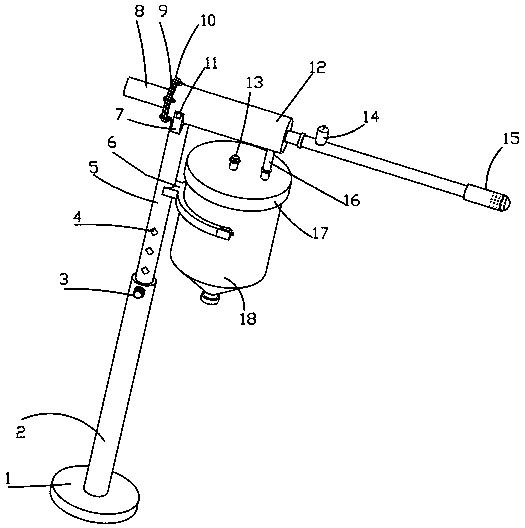
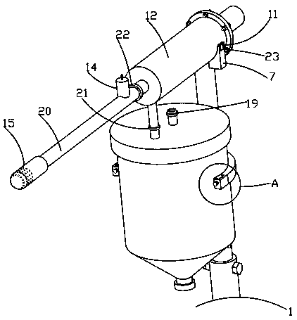
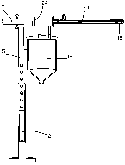
[0032] Such as Figure 1-6 The shown respiratory nursing sputum suction device includes a bottom plate 1 and an electric push rod 8, the electric push rod 8 is electrically connected to a power supply, the top of the bottom plate 1 is fixedly connected to a sleeve 2, and the sleeve 2 is slidably connected to a The positioning bolt 3 and the casing 2 are slidably connected with the sliding rod 5 through the sliding hole opened, and the positioning hole 4 is evenly and fixedly connected on the sliding rod 5, the positioning bolt 3 is slidingly connected with the positioning hole 4, and the sliding rod 5 in the sliding sleeve 2 , the sliding bar 5 drives the different positioning holes 4 to move to the positioning bolt 3, so that the sliding bar 5 facilitates the movement of the needle tube 12 to different heights, making the device suitable for use by medical staff of different heights, and improving adaptability;

[0033]The side wall of the upper end in the slide bar 5 is fixe...

Embodiment 2

[0035] Such as Figure 1-6 As shown, a suction device for nursing care in the respiratory department includes a bottom plate 1 and an electric push rod 8, the electric push rod 8 is electrically connected to a power supply, the top of the bottom plate 1 is fixedly connected to a sleeve 2, and the sleeve 2 is slidably connected to a The positioning bolt 3 and the casing 2 are slidably connected with the sliding rod 5 through the opened sliding hole, and the positioning hole 4 is evenly and fixedly connected on the sliding rod 5, the positioning bolt 3 is slidingly connected with the positioning hole 4, and the upper side wall of the sliding rod 5 is fixedly connected There is a first support plate 6, the first support plate 6 is connected with a connection structure, the connection structure is connected with a liquid accumulation bottle 18, the top of the liquid accumulation bottle 18 is threaded with a second cap 17, and the through hole at the top of the second cap 17 is fixe...

Embodiment 3

[0037] Such as Figure 1-6 As shown, a suction device for nursing care in the respiratory department includes a bottom plate 1 and an electric push rod 8, the electric push rod 8 is electrically connected to a power supply, the top of the bottom plate 1 is fixedly connected to a sleeve 2, and the sleeve 2 is slidably connected to a The positioning bolt 3 and the casing 2 are slidably connected with the sliding rod 5 through the opened sliding hole, and the positioning hole 4 is evenly and fixedly connected on the sliding rod 5, the positioning bolt 3 is slidingly connected with the positioning hole 4, and the upper side wall of the sliding rod 5 is fixedly connected There is a first support plate 6, the first support plate 6 is connected with a connection structure, the connection structure is connected with a liquid accumulation bottle 18, the top of the liquid accumulation bottle 18 is threaded with a second cap 17, and the through hole at the top of the second cap 17 is fixe...


PUM


Abstract

The invention relates to the technical field of respiratory department sputum suction nursing equipment, and particularly discloses a respiratory department nursing sputum suction device which comprises a bottom plate and an electric push rod, the bottom plate is provided with a sleeve, the sleeve is provided with a positioning bolt, the sleeve is provided with a sliding rod, the sliding rod is provided with a positioning hole, the positioning bolt is in sliding connection with the positioning hole, and the sliding rod is provided with a first supporting plate. The first supporting plate is provided with a connecting structure, the connecting structure is provided with a hydrops bottle, the hydrops bottle is provided with a second cap, the second cap is provided with an air outlet pipe anda connecting pipe, the air outlet pipe is provided with a first one-way valve, the connecting pipe is provided with a second one-way valve, the connecting pipe is provided with a needle tube, and theneedle tube is provided with a first cap provided with an electric push rod, the electric push rod is provided with a first piston, the needle tube is provided with a rubber tube, and a third one-wayvalve, an adjusting tube and a suction tube are arranged on the rubber tube. According to the sputum suction device, sputum can be scattered through the suction pipe, the volume is reduced, suction of the suction pipe is facilitated, the suction pipe is prevented from being blocked by the sputum, meanwhile, the suction pipe is conveniently driven to suck the sputum at different positions, and thesuction effect is improved.

Description

technical field [0001] The invention relates to the technical field of sputum suction nursing equipment in the respiratory department, in particular to a sputum suction device for respiratory nursing care. Background technique [0002] Medical equipment is the most basic element of medical treatment, scientific research, teaching, institutions, and clinical disciplines, including professional medical equipment and household medical equipment. Medical equipment is the basic condition for continuously improving the level of medical science and technology, and it is also an important symbol of modernization. Equipment has become an important field of modern medical treatment. The development of medical treatment depends to a large extent on the development of instruments. Even in the development of the medical industry, its breakthrough of bottlenecks also plays a decisive role. There are three major classification methods advocated by medical equipment Classes, namely diagnost...

Claims


Application Information

Patent Timeline
IPC IPC(8): A61M1/00
CPCA61M1/0001A61M1/0023A61M1/84
Inventor 梁国莉
Owner 梁国莉
Learn More