A cranial drainage tube subtly implanted device

A drainage tube and stealth technology, which is applied in the field of cranial drainage tube sneak implantation device, can solve the problem that it is difficult to build a sneak tunnel under the scalp, and achieve the effect of precise control of length, small trauma, and thin tunnel

Active Publication Date: 2021-11-16
济南市传染病医院
View PDF12 Cites 1 Cited by
  • Summary
  • Abstract
  • Description
  • Claims
  • Application Information

AI Technical Summary

Problems solved by technology

[0006] Aiming at the deficiencies in the prior art, the purpose of the present invention is to provide a submerged implantation device for craniocerebral drainage tubes, which can solve the problem that it is difficult to establish a submerged tunnel under the scalp at present, and carry out submerged tunneling through a semi-nested structure. Established, after the cone core is drawn out, the end of the drainage tube can be matched with the groove and wing plate at the end of the outer cone, so that it can be led out along the established sneak tunnel under the traction of the outer cone, so as to achieve the purpose of the drainage tube sneaking under the scalp

Method used


Image

  • A cranial drainage tube subtly implanted device
  • A cranial drainage tube subtly implanted device
  • A cranial drainage tube subtly implanted device

Examples


Embodiment 1

[0043] In a typical embodiment of the present invention, such as Figure 1-Figure 11 As shown, the device used to construct the drainage tube submerged tunnel is given.

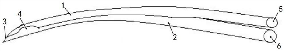
[0044] Such as figure 1 As shown, the submerged insertion device as a whole is a structure in which the outer cone 2 and the cone core 1 are engaged together, and only a part of it is engaged, and the other part is a separate structure; Under the action, it can penetrate into the scalp, thereby guiding the subsequent part to enter between the scalp 9 and the skull 8 for expansion, thereby forming a sneak tunnel; its end is a handle structure, and since both the outer cone and the inner cone need to apply force, the two Corresponding handle structures are fitted respectively, that is, the first handle 5 is fitted at the matching end of the cone core, and the second handle 6 is fitted at the end of the outer cone; a T-shaped structure is formed from the appearance.

[0045] Specifically, the outer cone is pro...

Embodiment 2

[0067] In another typical embodiment of the present invention, such as Figure 1-Figure 11 As shown, a method for submerged placement of a drainage tube using the device in Example 1 is given.

[0068] Engage the cone core with the outer cone, make the wedge fit with the groove, and form the submerged insertion device 7;

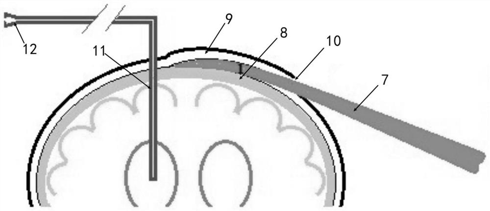
[0069] Determine the location of the skull perforation and the incision. The drainage tube is drawn out from the skull perforation, and the end of the drainage tube is a free end;

[0070] The tip of the device is pierced into the scalp from the incision, and the puncture part travels along the gap between the scalp and the skull until the tip reaches the place where the drainage tube enters the skull through the bone hole of the skull to establish a sneak tunnel;

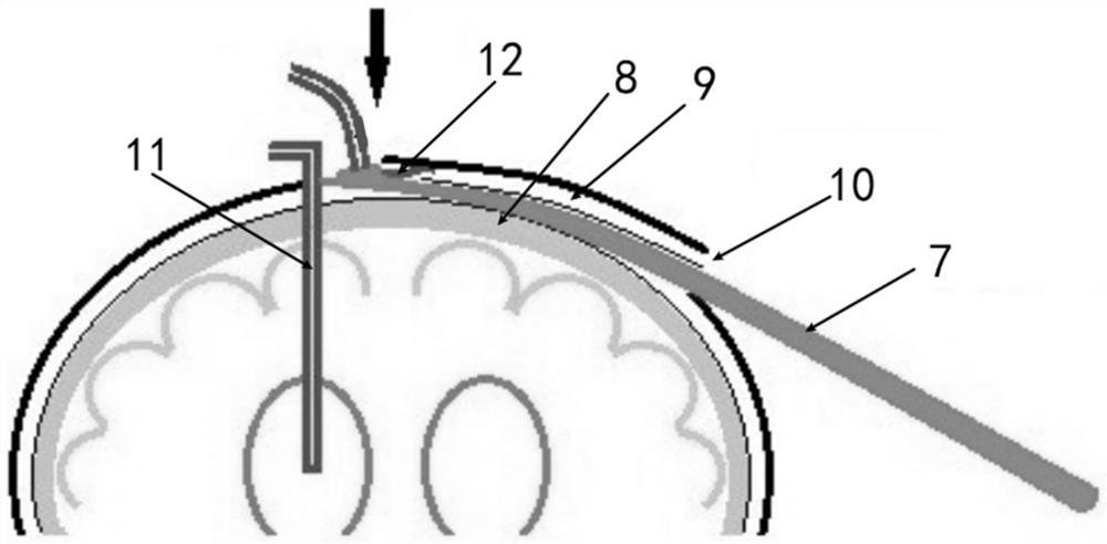
[0071] Pull out the cone core, and engage the end of the drainage tube with the wing plate;

[0072] Pull the second handle, and use the variable-diameter enlarged gap formed by the outer cone ...


PUM


Abstract

The invention discloses a craniocerebral drainage tube submerged implanting device, which comprises an outer cone and a cone core that cooperate with each other, the outer cone is provided with a groove extending from the front end to the middle and rear, the groove and the cone core Cooperate to form a half-wrap structure on the side of the front section of the cone core. The front end of the outer cone and the cone core cooperate together to form a tip. The outer cone is provided with a wing plate on the edge of the groove near the front end. When the cone core withdraws After detaching from the groove, the wing plate is used to cooperate with the enlarged groove with reduced diameter to engage the enlarged end of the drainage tube. When the outer cone is withdrawn, it can effectively and reliably pull the drainage tube back along the subcutaneous tunnel to achieve the purpose of stealth. The tunnel is formed at one time, and the drainage tube sneaking is completed at one time. One end of the semi-wrapped structure formed by the cone core and the outer cone, the size of the incision is similar to the diameter of the submerged tunnel constructed, and the distance and direction of the tunnel can be precisely controlled, avoiding scalp peeling caused by the use of vascular clamps to establish drainage tubes for submersion The problem of not being able to actually create a subcutaneous tunnel.

Description

technical field [0001] The invention relates to a submerged placement device for a craniocerebral drainage tube. Background technique [0002] The statements herein merely provide background information related to the present invention and do not necessarily constitute prior art. [0003] At present, whether it is performed manually or with the help of robots, the skull drilling and indwelling drainage tubes are widely used clinically in neurosurgery and related departments, and are widely used in the field of neurosurgery at home and abroad. It is suitable for intracerebral hematoma, acute obstructive hydrocephalus, chronic subdural hematoma, subdural effusion, intracerebral abscess, and other intracerebral tension cysts. Whether it is Dandy's drilling or the method of indwelling drainage tubes with the help of fine-hole drilling, it is widely used clinically because of its advantages of minimal invasiveness, easy operation, convenience, low incidence of complications and ...

Claims


Application Information

Patent Timeline
Patent Type & Authority Patents(China)
IPC IPC(8): A61M25/01
CPCA61M25/0102A61M25/0194A61M2025/0197
Inventor 荆柳
Owner 济南市传染病医院
Why Eureka
Try Eureka