Test tube cleaning device for clinical laboratory

The invention relates to a cleaning device and a technology of inspection department, which is applied in the field of inspection department and can solve the problems of difficulty in timely discharge, inability to clean the outer wall of the test tube, low cleaning efficiency, etc., and achieves the effect of improving efficiency, improving cleaning efficiency and ensuring cleaning effect.

Inactive Publication Date: 2020-06-05
张天明
View PDF10 Cites 5 Cited by
  • Summary
  • Abstract
  • Description
  • Claims
  • Application Information

AI Technical Summary

Problems solved by technology

The laboratory test tube cleaning device in the above patent has the following disadvantages: the outer wall of the test tube cannot be cleaned during use, and when the inner wall of t

Method used


Image

  • Test tube cleaning device for clinical laboratory
  • Test tube cleaning device for clinical laboratory
  • Test tube cleaning device for clinical laboratory

Examples


Embodiment 1

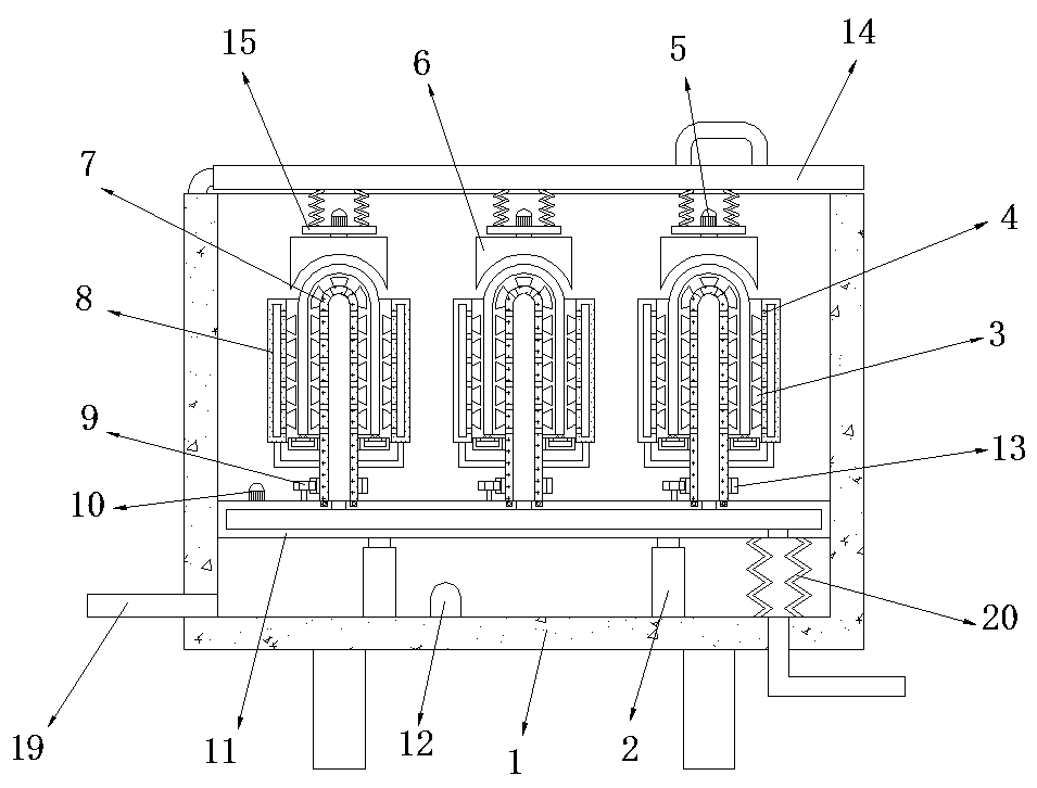
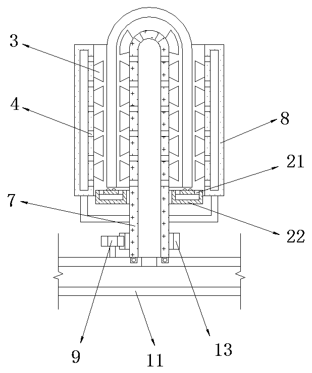
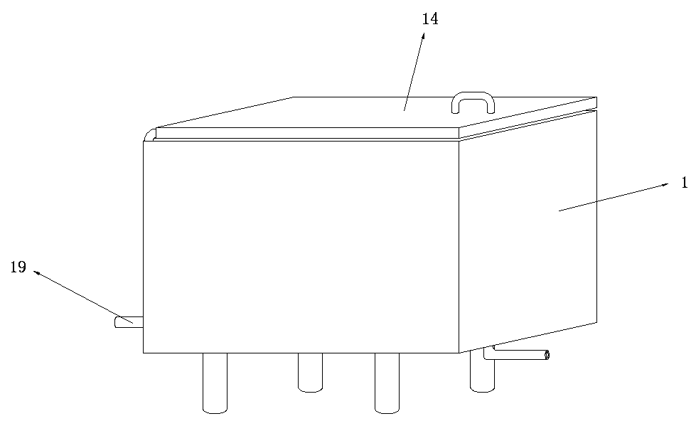
[0028] refer to Figure 1-3 , a test tube cleaning device for laboratory, including a box body 1, the bottom inner wall of the box body 1 is connected with a first electric telescopic rod 2 through a fastening bolt, and one end of the first electric telescopic rod 2 is connected with a lifting rod through a fastening bolt The pipe 11, the top of the lifting pipe 11 is plugged with evenly distributed outlet pipes 7, and the bottom of the outer wall of the outlet pipe 7 is connected to the limit ring 8 by fastening bolts, and the outer wall of the outlet pipe 7 and the inner wall of the limit ring 8 are provided with Evenly distributed water outlet holes 4, the bottom of the outer wall of the outlet pipe 7 is connected with a support plate 22 by fastening bolts, and the top of the support plate 22 is provided with evenly distributed perforations 21, and the inner wall of the bottom of the box body 1 is connected with a water pump by fastening bolts 12. The outer wall of the bott...

Embodiment 2

[0036] refer to figure 1 and Figure 4, a test tube cleaning device for laboratories. Compared with Embodiment 1, the tops of the inner walls on both sides of the outlet pipe 7 are connected with the same fixed rod 18 by fastening bolts, and the top of the fixed rod 18 is connected by fastening bolts. Connected with a second electric telescopic rod 17, one end of the second electric telescopic rod 17 is connected with an extension rod 16 by a spring, and the end of the extension rod 16 extending to the top outer wall of the outlet pipe 7 is connected with bristles by fastening bolts.

[0037] Working principle: when cleaning, the second electric telescopic rod 17 can reciprocate the extension rod 16, and the extension rod 16 pushes the test tube to reciprocate in the vertical direction to ensure the cleaning effect of the test tube.


PUM


Abstract

The invention discloses a test tube cleaning device for a clinical laboratory. The test tube cleaning device comprises a box, and a first electric telescopic rod is arranged on the inner wall of the bottom of the box. A lifting tube is arranged at one end of the first electric telescopic rod, and evenly distributed water outlet tubes are inserted into the top of the lifting tube. A limiting ring is arranged at the bottom of the circumferential outer wall of each water outlet tube, and evenly distributed water outlet holes are formed in the outer walls of the water outlet tubes and the inner walls of the limiting rings. Supporting discs are arranged at the bottoms of the circumferential outer walls of the water outlet tubes, and evenly distributed via holes are formed in the tops of the supporting discs. A water pump is arranged on the inner wall of the bottom of the box. When the test tube cleaning device is used, water in the clearances between the inner walls of test tubes and the water outlet tubes and the clearances between the outer walls of the test tubes and the limiting rings is drawn by the supporting discs, it is avoided that during water flow flushing, dirty water is gathered between the inner walls of the test tubes and the water outlet tubes or between the outer walls of the test tubes and the limiting rings and can hardly flow out in time, and consequently the cleaning effect is influenced, and the test tube flushing efficiency is improved.

Description

technical field [0001] The invention relates to the technical field of laboratories, in particular to a test tube cleaning device for laboratories. Background technique [0002] The laboratory uses a lot of test tubes every day. The used test tubes need to be cleaned for the next use because the inner wall is stained with liquid or adhered to solid substances. At present, the cleaning of test tubes is generally done manually. The rotation on the inner wall of the test tube realizes the cleaning of the test tube. In this cleaning method, a person needs to wear a medical glove and hold a test tube brush, and the work efficiency is low. [0003] After searching, the Chinese patent application number is CN201520022963.1, which discloses a test tube cleaning device for laboratory, including a transmission box, a hydraulic cylinder, a cleaning pool, a drive motor, an operating table, a pressure plate, a test tube and a brush handle. The upper end of the operation table is fixed w...

Claims


Application Information

Patent Timeline
IPC IPC(8): B08B9/28B08B9/36
CPCB08B9/28B08B9/36
Inventor 不公告发明人
Owner 张天明
Why Eureka
Try Eureka