Upward-90-degree bending double-bending die strip and bending machine

A bending die and bending machine technology, applied in the directions of forming tools, feeding devices, positioning devices, etc., can solve the problems that the section cannot be changed, the installation and debugging are complicated, the rolling section and the theoretical design difference, etc. efficiency, improving bending efficiency, and simplifying the structure

Pending Publication Date: 2020-06-05
ANHUI KINGPOWER EQUIP & MOLD MFR
View PDF0 Cites 2 Cited by
  • Summary
  • Abstract
  • Description
  • Claims
  • Application Information

AI Technical Summary

Problems solved by technology

[0002] At present, the labyrinth grooves of the side panels of the refrigerator and the top panel of the refrigerator are generally realized by means of rolling mills. The existing rolling mills have the following disadvantages: (1) the section cannot be changed once it is determined; (2) it is very difficult to install and debug. It is complicated and requires very professional installation and commissioning personnel; (3) It cannot be compatible with sheets with too large differences in thickness and material; (4) There are some differences between the rolling section and the theoretical design
In view of the above problems, a bending machine is used to bend the side panels and the top panel of the refrigerator into the required labyrinth grooves. However, the existing bending machine adopts the limitation of multiple bending methods, which makes the upper bending part and the lower bottom plate in a small 90-degree bends or clamped bends that cannot be achieved when there is a gap

Method used


Image

  • Upward-90-degree bending double-bending die strip and bending machine
  • Upward-90-degree bending double-bending die strip and bending machine
  • Upward-90-degree bending double-bending die strip and bending machine

Examples


Embodiment Construction

[0024] The following will clearly and completely describe the technical solutions in the embodiments of the present invention with reference to the accompanying drawings in the embodiments of the present invention. Obviously, the described embodiments are only some, not all, embodiments of the present invention. Based on the embodiments of the present invention, all other embodiments obtained by persons of ordinary skill in the art without making creative efforts belong to the protection scope of the present invention.

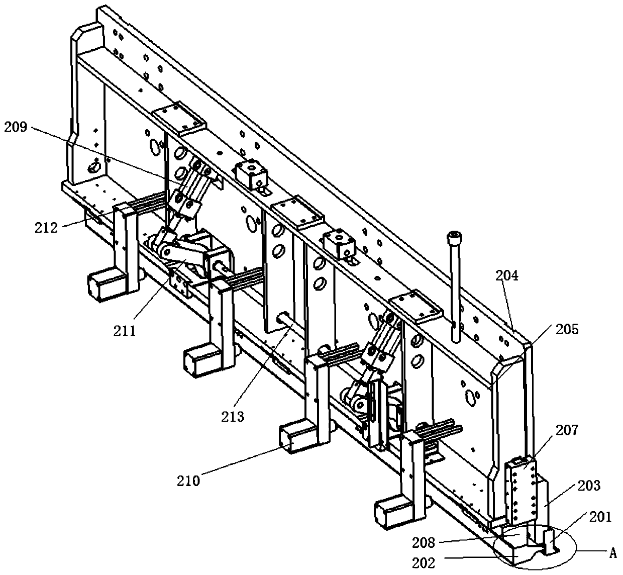
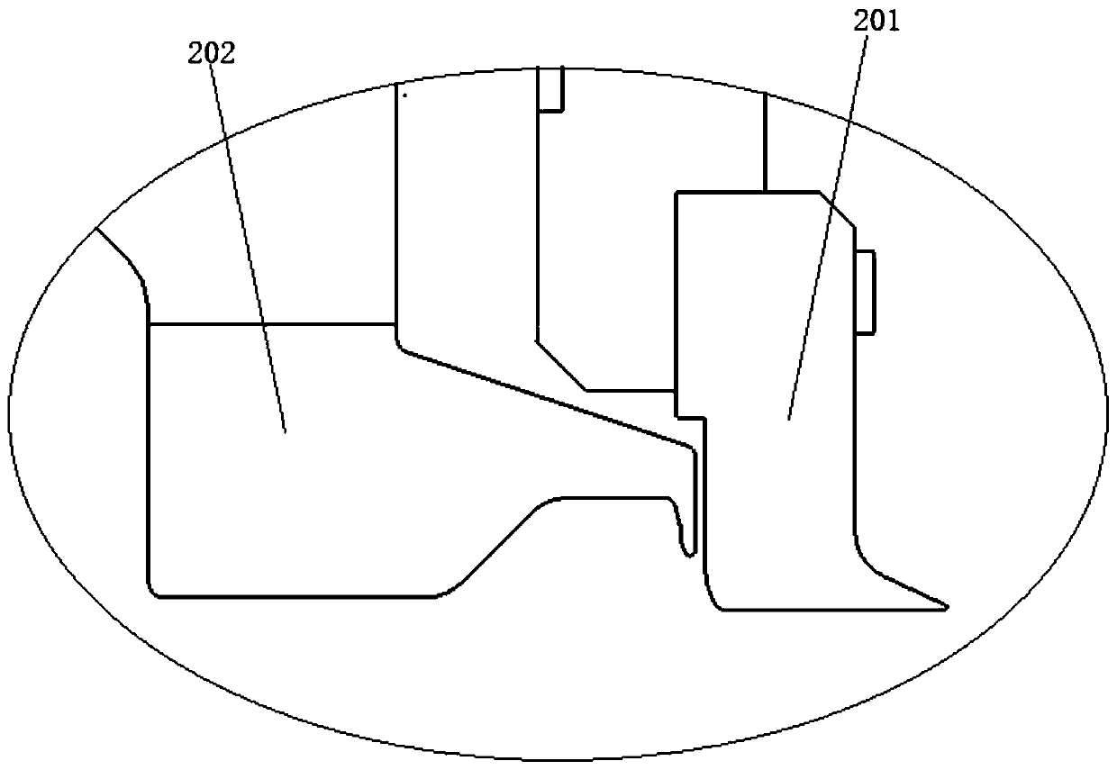
[0025] Such as figure 1 and figure 2 As shown, a double-bending mold strip bent upwards at 90 degrees, the double-bending mold strip includes a first bending mold strip 201 and a second bending mold strip 202, and the second bending mold strip 202 passes through the first bending mold strip The translation mechanism of the second bending mold bar can be horizontally moved on the side of the first bending mold bar 201; the first bending mold bar 201 includes ...


PUM


Abstract

The invention discloses an upward-90-degree bending double-bending die strip and a bending machine. The double-bending die strip comprises a first bending die strip and a second bending die strip. Thesecond bending die strip is horizontally and movably arranged on one side of the first bending die strip through a second bending die strip horizontal moving mechanism. The first bending die strip atleast comprises a pressing face, a bending angle is formed at the front end of the pressing face, and the bending angle is inwards bent by the acute angle. The side, close to the first bending die strip, of the second bending die strip is provided with a bending face, and the lower end of the bending face downwards extends in a hook shape. The bending machine comprises a bending swinging mechanism, a bending overturning mechanism, a lower die mechanism, a conveying mechanism and a side positioning mechanism. A die head of the first bending die strip is horizontally arranged, the second bending die strip is vertically arranged, 90-degree bending or clamping bending of a plate in the small gap can be achieved, and the bending efficiency is improved.

Description

technical field [0001] The invention relates to an upward 90-degree double-bending mold bar and a bending machine, belonging to the technical field of bending equipment. Background technique [0002] At present, the labyrinth grooves of the side panels of the refrigerator and the top panel of the refrigerator are generally realized by means of rolling mills. The existing rolling mills have the following disadvantages: (1) the section cannot be changed once it is determined; (2) it is very difficult to install and debug. It is complicated and requires very professional installation and commissioning personnel; (3) It cannot be compatible with sheets with too large differences in thickness and material; (4) There are some differences between the rolling section and the theoretical design. In view of the above problems, a bending machine is used to bend the side panels and the top panel of the refrigerator into the required labyrinth grooves. However, the existing bending machi...

Claims


Application Information

Patent Timeline
Patent Type & Authority Applications(China)
IPC IPC(8): B21D37/12B21D11/22B21D11/00B21D43/02
CPCB21D11/00B21D11/22B21D37/12B21D43/027
Inventor 陈安伟陈轩孙佳美
Owner ANHUI KINGPOWER EQUIP & MOLD MFR
Why Eureka
Try Eureka