A mechanical press brake lubrication system

A lubrication system and mechanical pressure technology, applied in the field of mechanical press brake lubrication system, can solve problems such as difficulty in resetting the slider, inability to stop in time, and mechanical press brake slippage, etc., to improve the sufficient lubrication effect, prolong the residence time, avoid The effect of a pulley accident

Active Publication Date: 2020-09-08
RONGCHENG HUADONG METAL FORMING MACHINERY +3
View PDF10 Cites 0 Cited by
  • Summary
  • Abstract
  • Description
  • Claims
  • Application Information

AI Technical Summary

Problems solved by technology

[0003] When the mechanical press and the automatic feeding of the robot are operated in a single stroke state, the brake needs to be combined and disengaged frequently. With long-term and high-frequency operation, the sealing ring on the brake piston will wear out quickly due to lack of lubricating oil. When the wear reaches a certain level, air leakage will occur, causing the braking torque to decrease, causing the brake of the mechanical press to slip, and the slider stop position is not allowed to cause waste products. In an emergency, it will not be able to stop in time, and even a block will occur. Very likely to cause safety accidents
Moreover, it is also difficult to reset the slider after the brake slips.
[0004] In order to improve the lubrication of the brake piston sealing ring, attempts have been made in the prior art. At present, the commonly used solution includes a pressure tank, a lubricator and a channel for lubricating the piston sealing ring. The air channel, that is, the air intake and exhaust share the same channel. Although the above solution improves the lubrication effect to a certain extent, the lubrication effect is not good
The root cause of the poor lubricating effect of the above scheme is that the air intake and the air outlet share the same channel, and the gas with a high concentration of oil mist pushes the gas with a low oil mist concentration inside the channel to move forward during the intake, which will cause The dilution of oil mist; when the gas returns to the original path when exhausting, the gas with high concentration of oil mist will be discharged first, which will cause the oil mist to not circulate effectively in the piston cavity of the brake, and the oil mist will not circulate for a long time. If it is not smooth, the oil mist concentration at the inner sealing ring of the brake will be low, and the lubrication at the sealing ring will be insufficient, which will aggravate the wear of the sealing ring, which will seriously affect the working effect, reliability and service life of the brake, and reduce the accuracy and safety of the machine tool. sex

Method used

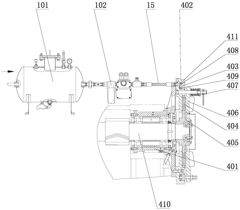
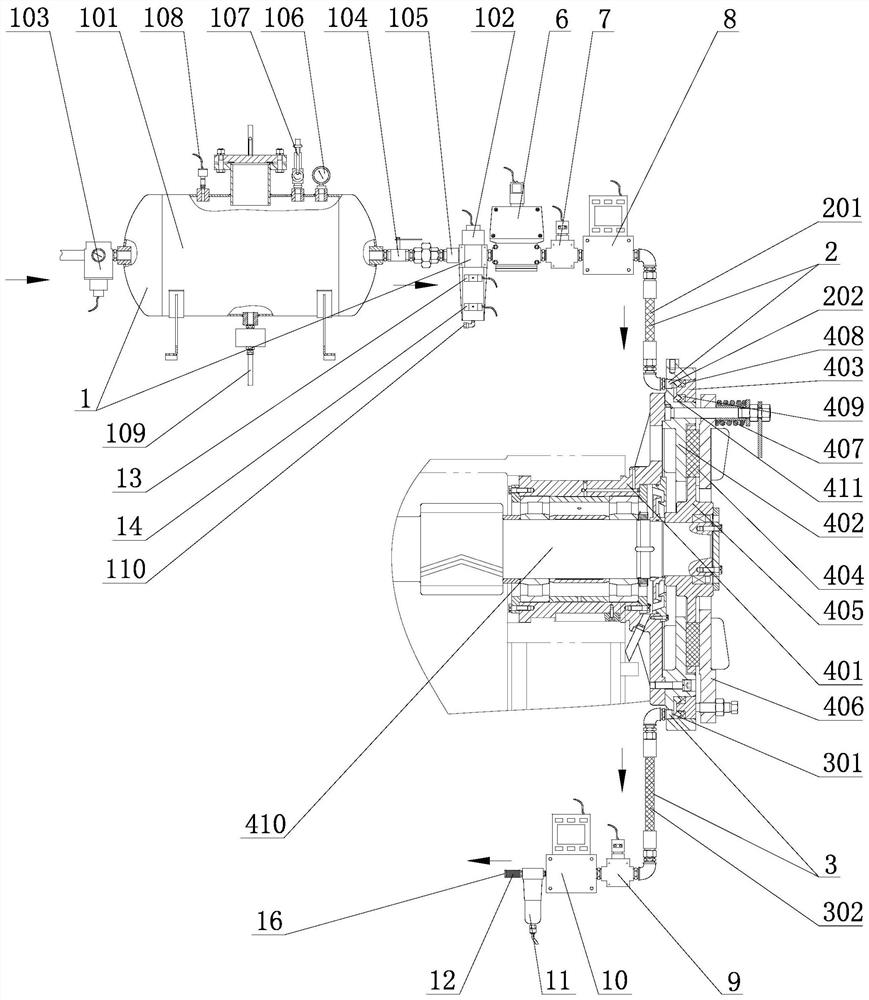
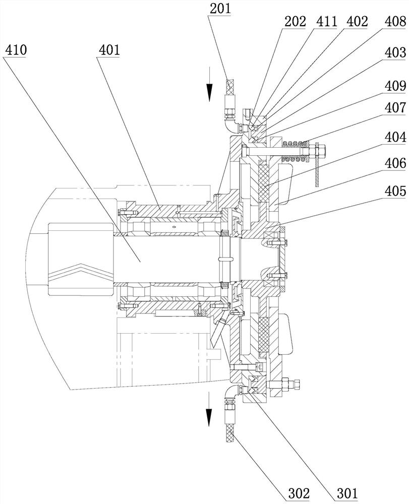

Image

  • A mechanical press brake lubrication system
  • A mechanical press brake lubrication system
  • A mechanical press brake lubrication system

Examples


Embodiment Construction

[0035] In order to explain the overall concept of the present invention more clearly, the following will be described in detail by way of examples in conjunction with the accompanying drawings.

[0036] In the following description, many specific details are set forth in order to fully understand the present invention. However, the present invention can also be implemented in other ways different from those described here. Therefore, the protection scope of the present invention is not limited by the specific details disclosed below. EXAMPLE LIMITATIONS.

[0037]Each embodiment in this specification is described in a progressive manner, the same and similar parts of each embodiment can be referred to each other, and each embodiment focuses on the differences from other embodiments.

[0038] In the present invention, the terms "inner side", "outer side", "upper", "lower", "A", "B" are used for descriptive purposes only, and are not to be understood as indicating or implying rel...


PUM


Abstract

The invention relates to a lubricating system for a brake of a mechanical press, comprising a brake, an oil mist gas supply mechanism, an air intake air path and an exhaust air path. The oil mist gas supply mechanism provides oil mist gas; It communicates with the piston chamber through the brake seat; one end of the exhaust air path communicates with the exhaust end, and the other end communicates with the piston chamber through the brake seat, and the air intake air path and the exhaust air path do not overlap. The existing lubricating system adopts the design of the same channel for the air intake and exhaust, resulting in poor oil mist circulation, resulting in low oil mist concentration at the sealing ring, and the sealing ring is still severely worn. The non-overlapping technical structure of the air and gas paths realizes the circulation of oil mist inside the brake, effectively lubricates the sealing ring for a long time, and reduces the wear of the sealing ring. Coupled with intelligent detection means, it can realize the intelligent measurement and control lubrication of the brake, prolong the service life of the brake, and has the advantages of high reliability and environmental protection.

Description

Technical field: [0001] The invention relates to the technical field of forging machine tools, in particular to a lubricating system for a mechanical press brake. Background technique: [0002] The brake is one of the main components of a mechanical press. At present, the interior of the existing brake mainly adopts a piston-type technical structure with a sealing ring, and the on-off action of the brake is controlled through the cooperation of air pressure, sealing ring, piston, spring and other components to realize the connection action of the entire transmission system. The brake and the clutch adopt the pneumatic interlocking control method. When the press stroke is opened, the electromagnetic double valve and the two-position three-way electromagnetic valve act simultaneously, and the compressed air quickly enters the brake through the double valve to disengage the brake disc, and then the brake is ventilated to drive the transmission. When the mechanism is running an...

Claims


Application Information

Patent Timeline
Patent Type & Authority Patents(China)
IPC IPC(8): B21J3/00
CPCB21J3/00
Inventor 彭鑫亮邱玉良蔺永诚岳振明陈明松张存生何道广李永涛周英
Owner RONGCHENG HUADONG METAL FORMING MACHINERY
Why Eureka
Try Eureka