


Quick Research
Generate reliable direction feasibility study reports for your R&D in just a few steps.

Technical Q&A
Discover and master advanced knowledge NOW. Basics, ideas, possibilities, all at once.

Find Solutions
As an expert in R&D theories, this can generate solutions to your technical problems instantly.

Evaluate Feasibility
Analyze your overall solution with one click, know your potential R&D risks in advance.

Monitor Landscape
Get weekly tech updates, stay abreast of the latest tech innovations and key insights.
A kind of flexible and quick clamping fixture for rotary machine tool and clamping method
A technology of machine tools and fixtures, which is applied in the field of flexible and fast clamping fixtures and clamping, can solve the problems of fast positioning and versatility of fixtures that are not well solved, and achieve easy use, easy flexible automatic production, and reduce the difficulty of production and handling Effect
- Summary
- Abstract
- Description
- Claims
- Application Information
AI Technical Summary
Problems solved by technology
Method used
Image

Examples
Embodiment 1
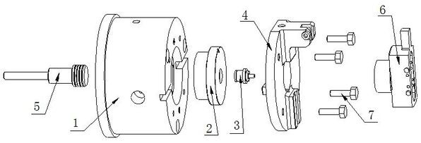
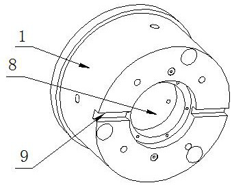
[0044] A flexible and fast clamping fixture for a rotary machine tool includes a main body 1, an anti-rotation positioning block 4, a zero point positioning module 2, a self-positioning pull stud 3, a hydraulic cylinder piston 5, a general clamp 6 for small and medium pieces, and a connecting bolt 7. The hydraulic cylinder piston 5 is located on one side of the main body 1, and the other side of the main body 1 is provided with a zero point positioning module 2, and the zero point positioning module 2 is directly connected with the part through the self-positioning pull stud 3. When the part is small, it cannot be connected with the self-positioning pull stud 3. When the nails 3 are directly connected, the self-positioning pull nail 3 is connected to the general fixture 6 for small and medium pieces, and the general fixture 6 for small and medium pieces is connected to the parts. An anti-rotation positioning block 4 , the anti-rotation positioning block 4 is connected with the ...
Embodiment 2
[0046] A flexible and fast clamping fixture for a rotary machine tool includes a main body 1, an anti-rotation positioning block 4, a zero point positioning module 2, a self-positioning pull stud 3, a hydraulic cylinder piston 5, a general clamp 6 for small and medium pieces, and a connecting bolt 7. The hydraulic cylinder piston 5 is located on one side of the main body 1, and the other side of the main body 1 is provided with a zero point positioning module 2, and the zero point positioning module 2 is directly connected with the part through the self-positioning pull stud 3. When the part is small, it cannot be connected with the self-positioning pull stud 3. When the nails 3 are directly connected, the self-positioning pull nail 3 is connected to the general fixture 6 for small and medium pieces, and the general fixture 6 for small and medium pieces is connected to the parts. An anti-rotation positioning block 4 , the anti-rotation positioning block 4 is connected with the ...
Embodiment 3
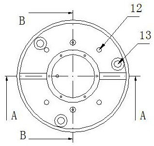
[0056] A flexible and fast clamping method for a rotary machine tool. Step 1: Connect the hydraulic cylinder piston 5 with the machine tool hydraulic cylinder, cooperate the zero point positioning system with the main body 1 to form a clamp base, and fasten the clamp base to the machine tool spindle or On the rotary table, install and fix the anti-rotation positioning block 4 on the fixture base, fill the hydraulic oil circuit of the main body 1 and the anti-rotation positioning block 4 with hydraulic oil, and tighten all hydraulic oil circuit plugs 10 .
[0057] Step 2: Workpiece positioning.
[0058] Step 3: Turn off the hydraulic pump, clamp the self-positioning pull stud 3 together with the workpiece and the small and medium-sized universal fixtures on the fixture base to achieve accurate positioning, and then completely fasten the workpiece to the clamping body through the top of the tailstock of the machine tool.
[0059] Step 4: start the hydraulic cylinder of the machi...
PUM
 Abstract
Description
Claims
Application Information
 - R&D Engineer
- R&D Manager
- IP Professional
- Industry Leading Data Capabilities
- Powerful AI technology
- Patent DNA Extraction
Browse by: Latest US Patents, China's latest patents, Technical Efficacy Thesaurus, Application Domain, Technology Topic, Popular Technical Reports.
© 2024 PatSnap. All rights reserved.Legal|Privacy policy|Modern Slavery Act Transparency Statement|Sitemap|About US| Contact US: help@patsnap.com