A rotary machine tool fixture and a method for clamping workpieces
A machine tool fixture and anti-rotation technology, which is applied to metal processing mechanical parts, clamping, manufacturing tools, etc., can solve the problems of scrapping of processed parts, and achieve the effect of short replacement time, universality, and flexible automatic production.
- Summary
- Abstract
- Description
- Claims
- Application Information
AI Technical Summary
Problems solved by technology
Method used
Image
Examples
Embodiment 1
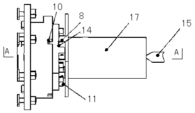
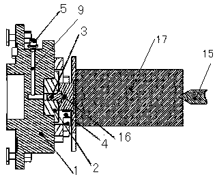
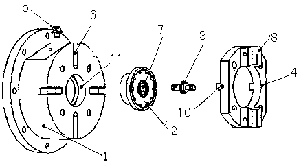
[0031] Such as Figures 1 to 3 As shown, a rotary machine tool fixture includes a main shaft connecting body 1, a blank 17 and a top 15. The main shaft connecting body 1 is provided with a positioning ring 11, a hydraulic channel 9, a hydraulic joint 5 and a plurality of key grooves 6. The key grooves 6 are evenly distributed around the positioning ring 11, the zero point positioning module 2 is installed in the positioning ring 11, the zero point positioning module 2 is provided with a central hole 7, one end of the hydraulic channel 9 is connected with the hydraulic joint 5, and the other One end communicates with the central hole 7, the hydraulic joint 5 is connected with a hydraulic pump, the central hole 7 is equipped with a pull stud 5, the main shaft connecting body 1 is connected with an anti-rotation positioning block 4 through bolts, and the anti-rotation positioning The block 4 is provided with a positioning key 10 that cooperates with the keyway 6, and the anti-rot...
Embodiment 2
[0034] Such as Figures 1 to 3 As shown, a rotary machine tool fixture includes a main shaft connecting body 1, a blank 17 and a top 15. The main shaft connecting body 1 is provided with a positioning ring 11, a hydraulic channel 9, a hydraulic joint 5 and a plurality of key grooves 6. The key grooves 6 are evenly distributed around the positioning ring 11, the zero point positioning module 2 is installed in the positioning ring 11, the zero point positioning module 2 is provided with a central hole 7, one end of the hydraulic channel 9 is connected with the hydraulic joint 5, and the other One end communicates with the central hole 7, the hydraulic joint 5 is connected with a hydraulic pump, the central hole 7 is equipped with a pull stud 5, the main shaft connecting body 1 is connected with an anti-rotation positioning block 4 through bolts, and the anti-rotation positioning The block 4 is provided with a positioning key 10 that cooperates with the keyway 6, and the anti-rot...
Embodiment 3
[0039] Such as Figures 1 to 3 As shown, a rotary machine tool fixture includes a main shaft connecting body 1, a blank 17 and a top 15. The main shaft connecting body 1 is provided with a positioning ring 11, a hydraulic channel 9, a hydraulic joint 5 and a plurality of key grooves 6. The key grooves 6 are evenly distributed around the positioning ring 11, the zero point positioning module 2 is installed in the positioning ring 11, the zero point positioning module 2 is provided with a central hole 7, one end of the hydraulic channel 9 is connected with the hydraulic joint 5, and the other One end communicates with the central hole 7, the hydraulic joint 5 is connected with a hydraulic pump, the central hole 7 is equipped with a pull stud 5, the main shaft connecting body 1 is connected with an anti-rotation positioning block 4 through bolts, and the anti-rotation positioning The block 4 is provided with a positioning key 10 that cooperates with the keyway 6, and the anti-rot...
PUM
 Abstract
Description
Claims
Application Information
 - R&D
- Intellectual Property
- Life Sciences
- Materials
- Tech Scout
- Unparalleled Data Quality
- Higher Quality Content
- 60% Fewer Hallucinations
Browse by: Latest US Patents, China's latest patents, Technical Efficacy Thesaurus, Application Domain, Technology Topic, Popular Technical Reports.
© 2025 PatSnap. All rights reserved.Legal|Privacy policy|Modern Slavery Act Transparency Statement|Sitemap|About US| Contact US: help@patsnap.com


