Steel component length fixing mechanism

A steel member, fixed-length technology, used in positioning devices, maintenance and safety accessories, metal processing machinery parts, etc., can solve the problems of low measurement and positioning work efficiency of steel members, unfavorable cutting of steel members, and low cutting accuracy. , to reduce the difficulty of operation, reduce cutting errors, and improve positioning efficiency.

Active Publication Date: 2020-06-05
重庆玉带路工业科技有限公司
View PDF8 Cites 1 Cited by
  • Summary
  • Abstract
  • Description
  • Claims
  • Application Information

AI Technical Summary

Problems solved by technology

[0003] Since the length of the steel member cannot be determined, it is necessary to cut the steel member according to the required length during use. The current cutting method is to use a scale to measure the steel member, then mark the measurement position, and then pass Cutting steel components wit

Method used


Image

  • Steel component length fixing mechanism
  • Steel component length fixing mechanism
  • Steel component length fixing mechanism

Examples


Embodiment 1

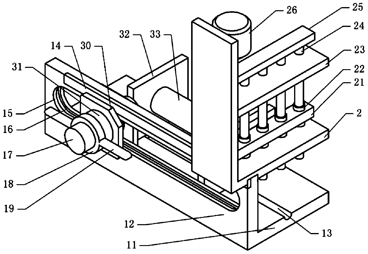
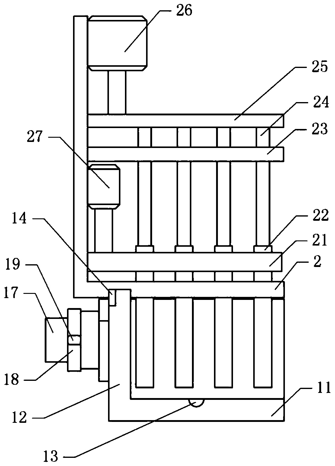
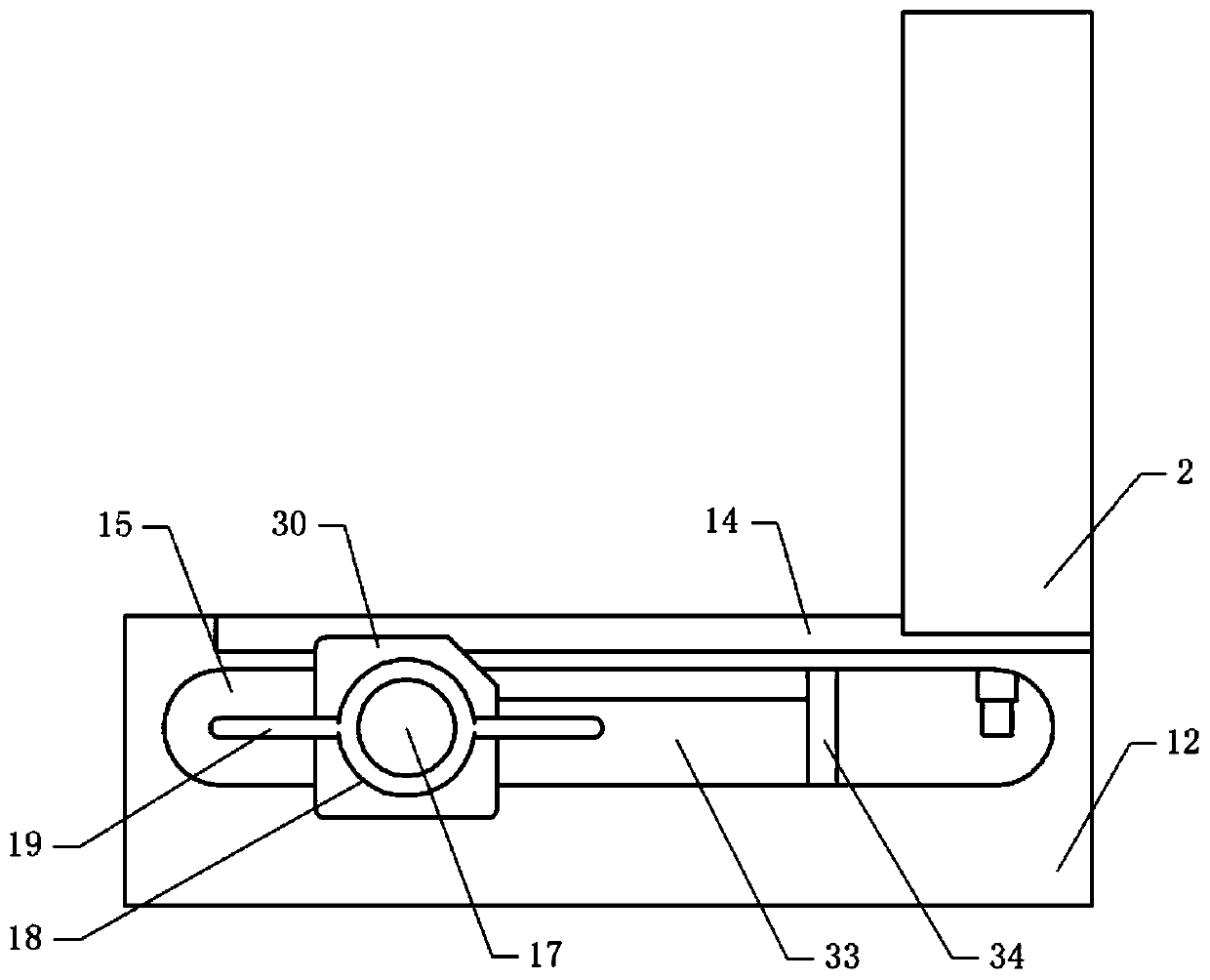
[0041] Basic as attached figure 1 , attached figure 2 And attached image 3 As shown, a length-fixing mechanism for steel members includes a first plate 11 and a second plate 12 integrally formed with the first plate 11, and the first plate 11 and the second plate 12 form an L-shaped plate.

[0042] The middle part of the second plate 12 has a chute 15, and the side wall of the chute 15 has a ball groove 16, and the horizontal sliding in the chute 15 is connected with a positioning shaft 17, and the positioning shaft 17 can slide along the width direction of the chute 15. combined with Figure 5 As shown, a ball 36 is welded on the positioning shaft 17, and the ball 36 is slidingly matched with the ball groove 16, and there is a certain distance between the ball 36 and the ball groove 16.

[0043] as attached Figure 4 As shown, the positioning shaft 17 is sequentially provided with a pressing shaft 18 , a pressing shaft 31 , two clamping pieces and a first pressing plate...

Embodiment 2

[0053] The difference between embodiment two and embodiment one is that, as attached Figure 6 And attached Figure 7 As shown, the auxiliary shaft 24 is provided with a liquid channel 241 and has openings at both ends. The auxiliary shaft 24 includes an upper section and a lower section located in the fixed shaft 22. A bellows is arranged between the upper section and the lower section. The upper end of the bellows and the upper section are fastened The bolts are fixedly connected, the lower end of the bellows and the lower section are fixedly connected by fastening bolts, and the bellows connects the upper section and the lower section. The fixed shaft 22 is provided with a number of injection holes 221 along its axial direction, and the lower section is provided with a number of liquid holes communicating with the injection holes 221 along its axial direction.

[0054] The second sliding plate 25 is provided with a cavity 251 communicating with the upper section. The cavit...


PUM


Abstract

The invention relates to the technical field of fixed-length cutting, and discloses a steel component length fixing mechanism. The steel component length fixing mechanism comprises a first plate and asecond plate fixed to the first plate. A sliding groove is formed in the second plate, and a positioning shaft is horizontally and slidably connected in the sliding groove. A first extruding plate located on the first plate is fixed to one end of the positioning shaft, and the outer wall of the positioning shaft is in threaded connection with a compressing shaft. The top of the second plate is horizontally and slidably connected with a third plate, the third plate is vertically and slidably connected with a first sliding plate driven by a first driving part, and a plurality of hollow fixed shafts penetrating through the third plate are fixed to the first sliding plate. A second sliding plate vertically and slidably connected with the third plate and driven by a second driving part is arranged above the first sliding plate. A plurality of auxiliary shafts are fixed to the second sliding plate and located in the fixed shafts correspondingly, and the auxiliary shafts are horizontally andslidably connected with the fixed shafts. A dividing ruler is fixed to the side wall of the second plate. The steel component length fixing mechanism is simple in structure, a steel component can befast positioned, and cutting errors are reduced.

Description

technical field [0001] The invention relates to the technical field of fixed-length cutting, in particular to a steel component length-fixing mechanism. Background technique [0002] Steel members refer to steel structural composite members that can bear and transmit loads and are connected by steel plates, angle steels, channel steels, I-beams, welded or hot-rolled H-beams, cold-bent or welded through connectors. [0003] Since the length of the steel member cannot be determined, the steel member needs to be cut according to the required length during use. The current cutting method is to use a scale to measure the steel member, then mark the measurement position, and then pass Cutting steel components with cutting knives, etc. This method has high requirements for the skills and experience of the operator. For a novice, the cutting accuracy of this method is low, and the measurement and positioning of steel components The efficiency is not high, so it is not conducive to ...

Claims


Application Information

Patent Timeline
IPC IPC(8): B23Q3/18B23Q11/10B23Q11/00
CPCB23Q3/18B23Q11/0042B23Q11/10
Inventor 石永丹
Owner 重庆玉带路工业科技有限公司
Why Eureka
Try Eureka