A connector and a wiper

A connector and wiper arm technology, used in transportation and packaging, vehicle cleaning, vehicle maintenance, etc., can solve problems such as safety accidents, smashed windshields of vehicles, failures, etc., and achieve the effect of ensuring reliability.

Active Publication Date: 2021-08-27
XIAMEN FUKE CAR ACCESSORIES
View PDF5 Cites 0 Cited by
  • Summary
  • Abstract
  • Description
  • Claims
  • Application Information

AI Technical Summary

Problems solved by technology

Because its elastically deflected part is often fragile, it is easy to fail in vibration or multiple swings, causing the wiper blade and connector to be thrown out of the wiper arm, resulting in a safety accident
At the same time, because the elastic deflection part is prone to failure, the wiper blade and connector may fall from the wiper arm when disassembling and assembling the wiper blade and connector, thereby smashing the windshield of the vehicle

Method used


Image

  • A connector and a wiper
  • A connector and a wiper
  • A connector and a wiper

Examples


Embodiment 1

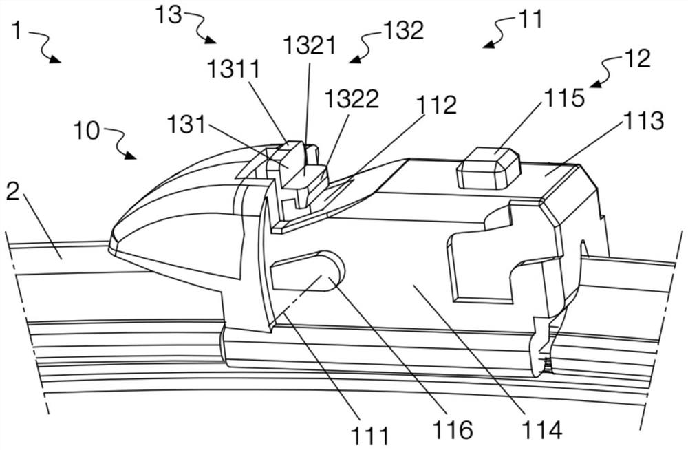
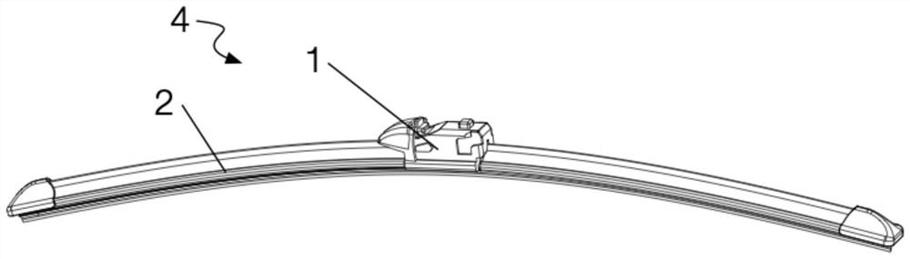
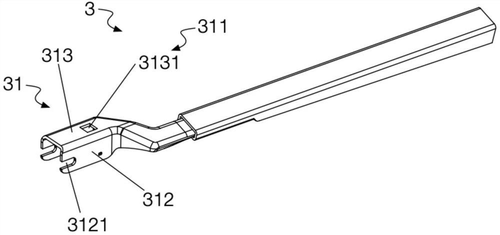
[0087] see figure 1 , figure 1 The connector 1 in the first embodiment is shown. The connector 1 is used to ensure the hinge relationship between the wiper blade 2 and the wiper arm 3 (see Figure 4 ).

[0088] Such as figure 1 As shown, the connector 1 in the first embodiment includes a fixing member 10 fixedly connected with the wiper blade 2 .

[0089] The fixing part 10 is provided with a body 11 , a blocking part 12 and a deforming part 13 .

[0090] Wherein, the main body 11 has two side surfaces 114 , a top surface 113 and a concave portion 112 . Protruding shafts 116 extending to both sides are provided on the two side surfaces 114 . The protruding shaft 116 is used to establish a hinge relationship with the wiper arm 3 to form a rotating shaft 111 for rotating the wiper arm 3 around the main body 11 . At the rear of the rotating shaft 111, the top surface 113 is provided with a first protrusion 115, the first protrusion 115 forms the aforementioned blocking por...

Embodiment 2

[0107] see Figure 8 and Figure 9 , Figure 8 The connector 1 in the second embodiment is shown. The connector 1 is used to ensure the hinge relationship between the wiper blade 2 and the wiper arm 3 (see Figure 11 ).

[0108] Such as Figure 8 As shown, the connector 1 in the second embodiment includes a fixed piece 10 fixedly connected with the wiper blade 2 , and a rotating piece 20 rotatably connected with the fixed piece 10 relative to the rotating shaft 111 .

[0109] Such as Figure 9 As shown, the fixing part 10 is provided with a body 11 , a blocking part 12 and a deforming part 13 .

[0110] Wherein, the main body 11 has two side surfaces 114 , a top surface 113 and a concave portion 112 . A rotating shaft 111 rotatably connected to the rotating member 20 is defined on the two side surfaces 114 . At the rear of the rotating shaft 111, the top surface 113 is provided with a first protrusion 115, the first protrusion 115 forms the aforementioned blocking port...

Embodiment 3

[0128] see Figure 16 , Figure 16 The connector 1 in the third embodiment is shown. The connector 1 is used to ensure the hinge relationship between the wiper blade 2 and the wiper arm 3 (see Figure 18 ).

[0129] Such as Figure 16 As shown, the connector 1 in the third embodiment includes a fixed piece 10 fixedly connected with the wiper blade 2 , and a rotating piece 20 rotatably connected with the fixed piece 10 relative to the rotating shaft 111 .

[0130] Wherein, the fixing member 10 is the same as Figure 9 The fixing member 10 in the second embodiment shown is completely the same, and will not be repeated here.

[0131] Such as Figure 16 As shown, the rotating member 20 is basically the same as the rotating member 20 in the second embodiment, the only difference is that in the third embodiment, the top wall 21 of the rotating member 20 is configured as a hinged relationship between the wiper blade 2 and the wiper arm 3 , the limiting surface 1321 is located ...


PUM


Abstract

The application discloses a connector and a wiper. Wherein, the fixing part connected with the wiper blade in the connector is provided with a blocking part located behind the rotating shaft and a deforming part located in front of the rotating shaft. Wherein, the blocking part is used to prevent the wiper arm from withdrawing backward after the wiper blade and the wiper arm establish a hinge relationship; the deformation part is provided with an upward limiting surface and is switched between the reset first state and the driven second state; In the first state, the limiting surface restricts the rotation of the wiper arm, preventing the wiper arm from going over the blocking portion and retreating backward; in the second state, the limiting surface moves forward and no longer restricts the rotation of the wiper arm. The present application also discloses a windshield wiper comprising the above-mentioned connector. By adopting the above technical solution, the connector can ensure that the wiper blade cannot be thrown out relative to the wiper arm after the hinged relationship between the wiper blade and the wiper arm is established.

Description

technical field [0001] The invention relates to the field of wipers, in particular to a connector and a wiper. Background technique [0002] The wipers used on vehicles are generally arranged on the windshield of the vehicle to scrape off rainwater or impurities falling on the windshield. It generally includes motors and wipers. Wherein, the wiper includes a wiper arm and a wiper blade assembly, and the wiper blade assembly includes a connector and a wiper blade. When connecting, the output shaft of the motor is connected to the wiper arm, and the wiper arm is connected to the wiper blade through a connector, and the wiper blade directly acts on the windshield of the vehicle. Since the wiper is in a working state, the wiper blade needs to follow the curvature of the windshield of the vehicle and swing slightly relative to the wiper arm, so the wiper arm and the wiper blade need to establish a hinged relationship. As the connector between the wiper arm and the wiper blade,...

Claims


Application Information

Patent Timeline
Patent Type & Authority Patents(China)
IPC IPC(8): B60S1/38B60S1/40
CPCB60S1/3849B60S1/386B60S1/4038
Inventor 王书屋
Owner XIAMEN FUKE CAR ACCESSORIES
Why Eureka
Try Eureka