A continuous heat treatment device for fasteners

A heat treatment device and fastener technology, applied in heat treatment furnaces, heat treatment equipment, drying gas layout, etc., can solve the problems of consuming a lot of time and experience, rusting fasteners, wasting water resources, etc., saving time and energy , to ensure subsequent use, the effect of saving water resources

Active Publication Date: 2021-08-10
重庆奇庆机电有限公司
View PDF0 Cites 2 Cited by
  • Summary
  • Abstract
  • Description
  • Claims
  • Application Information

AI Technical Summary

Problems solved by technology

[0003] 1. The existing fastener heat treatment cooling process usually uses artificial water pipes or other tools to sprinkle water on the surface of the fastener to cool the fastener, which takes a lot of time and experience, and the sprayed The water has not been able to be recycled reasonably, wasting water resources;
[0004] 2. After the fastener is cooled, some cold water will remain on the surface of the fastener. This cold water will affect the subsequent processing and storage of the fastener, which will easily cause the fastener to rust. If the external power supply is used to heat the fastener Drying the water on the surface of the firmware requires a lot of power consumption and increases the economic cost

Method used


Image

  • A continuous heat treatment device for fasteners
  • A continuous heat treatment device for fasteners

Examples


Embodiment Construction

[0018] The following will clearly and completely describe the technical solutions in the embodiments of the present invention with reference to the accompanying drawings in the embodiments of the present invention. Obviously, the described embodiments are only some, not all, embodiments of the present invention.

[0019] In describing the present invention, it should be understood that the terms "upper", "lower", "front", "rear", "left", "right", "top", "bottom", "inner", " The orientation or positional relationship indicated by "outside", etc. is based on the orientation or positional relationship shown in the drawings, and is only for the convenience of describing the present invention and simplifying the description, rather than indicating or implying that the referred device or element must have a specific orientation, so as to Specific orientation configurations and operations, therefore, are not to be construed as limitations on the invention.

[0020] refer to Figure ...


PUM


Abstract

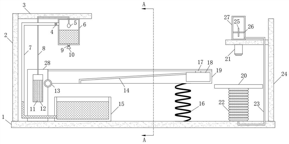
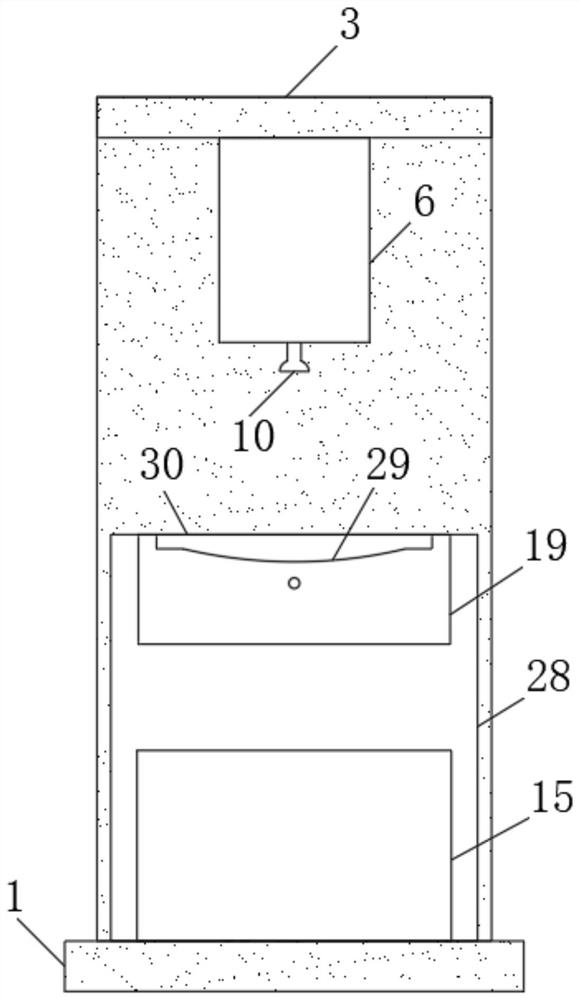
The invention discloses a continuous heat treatment device for fasteners, comprising a bottom plate, a cooling mechanism and a drying mechanism are arranged on the top of the bottom plate, the cooling mechanism includes a fixed column, and the side wall of the fixed column is rotatably connected with a heat conducting plate , the end of the heat conducting plate away from the fixed column is elastically connected to the bottom plate through a support spring, the upper wall of the bottom plate is fixedly connected with a first vertical plate, and the side wall near the upper end of the first vertical plate is fixedly connected with a first horizontal plate, so The inside of the fixed column is provided with a liquid storage chamber, the liquid storage chamber is equipped with a low boiling point evaporating liquid, the lower wall of the first horizontal plate is fixedly connected with a sprinkler box, and the upper wall of the liquid storage chamber communicates with the sprinkler box through a connecting pipe One end of the connecting pipe located in the sprinkler box is communicated with a balloon, and the lower wall of the sprinkler box is communicated with a sprinkler head through a water outlet pipe. The invention greatly saves people's time, energy and water resources, ensures the subsequent use of fasteners, and greatly saves electric energy.

Description

technical field [0001] The invention relates to the technical field of fastener heat treatment, in particular to a fastener continuous heat treatment device. Background technique [0002] Fasteners are widely used mechanical parts for fastening connections. In order to improve the performance of fasteners, heat treatment is usually performed on fasteners. In the process of heat treatment of fasteners, it is necessary to Fasteners are cooled, and the heat treatment cooling process of fasteners is usually carried out with cold water, but the existing fastener heat treatment cooling process has the following problems: [0003] 1. The existing fastener heat treatment cooling process usually uses artificial water pipes or other tools to sprinkle water on the surface of the fastener to cool the fastener, which takes a lot of time and experience, and the sprayed The water has not been able to be recycled reasonably, wasting water resources; [0004] 2. After the fastener is coole...

Claims


Application Information

Patent Timeline
Patent Type & Authority Patents(China)
IPC IPC(8): C21D9/00F26B21/00
CPCC21D9/0068F26B21/001
Inventor 张瑞雯曹淯翔
Owner 重庆奇庆机电有限公司
Why Eureka
Try Eureka