
Warp protection buckle

A technology for protecting buckles and warp yarns, applied in textiles, textiles, papermaking, looms, etc., can solve the problems of smooth rotation of warp protection devices, increased impact force, uneven wear position, etc., to improve replacement and maintenance efficiency and increase use. Longevity and the effect of reducing maintenance costs

Active Publication Date: 2020-06-05
QINGDAO KAISHUO MACHINERY TECH CO LTD
View PDF7 Cites 0 Cited by
  • Summary
  • Abstract
  • Description
  • Claims
  • Application Information

AI Technical Summary

Problems solved by technology

[0003] However, due to the need for repeated pretensioning during the operation of the textile machine, it is easy to cause wear and tear on the rotating shaft and the protective device, reducing the service life. At the same time, due to uneven wear positions, the pretensioning effect on the warp yarns is not stable, which is easy to cause warp yarns. Fracture, and the rotation process is prone to jumps due to the extrusion between the plane and the arc surface, which in turn increases the impact force and deforms the rotating device
[0004] To this end, a warp protection buckle is provided to solve the problem of wear and smooth rotation in the warp protection device

Method used


Image

  • Warp protection buckle
  • Warp protection buckle
  • Warp protection buckle

Examples


Embodiment Construction

[0027] The following will clearly and completely describe the technical solutions in the embodiments of the present invention with reference to the accompanying drawings in the embodiments of the present invention. Obviously, the described embodiments are only some, not all, embodiments of the present invention. Based on the embodiments of the present invention, all other embodiments obtained by persons of ordinary skill in the art without making creative efforts belong to the protection scope of the present invention.

[0028] see Figure 1 to Figure 6 , the present invention provides a technical solution:

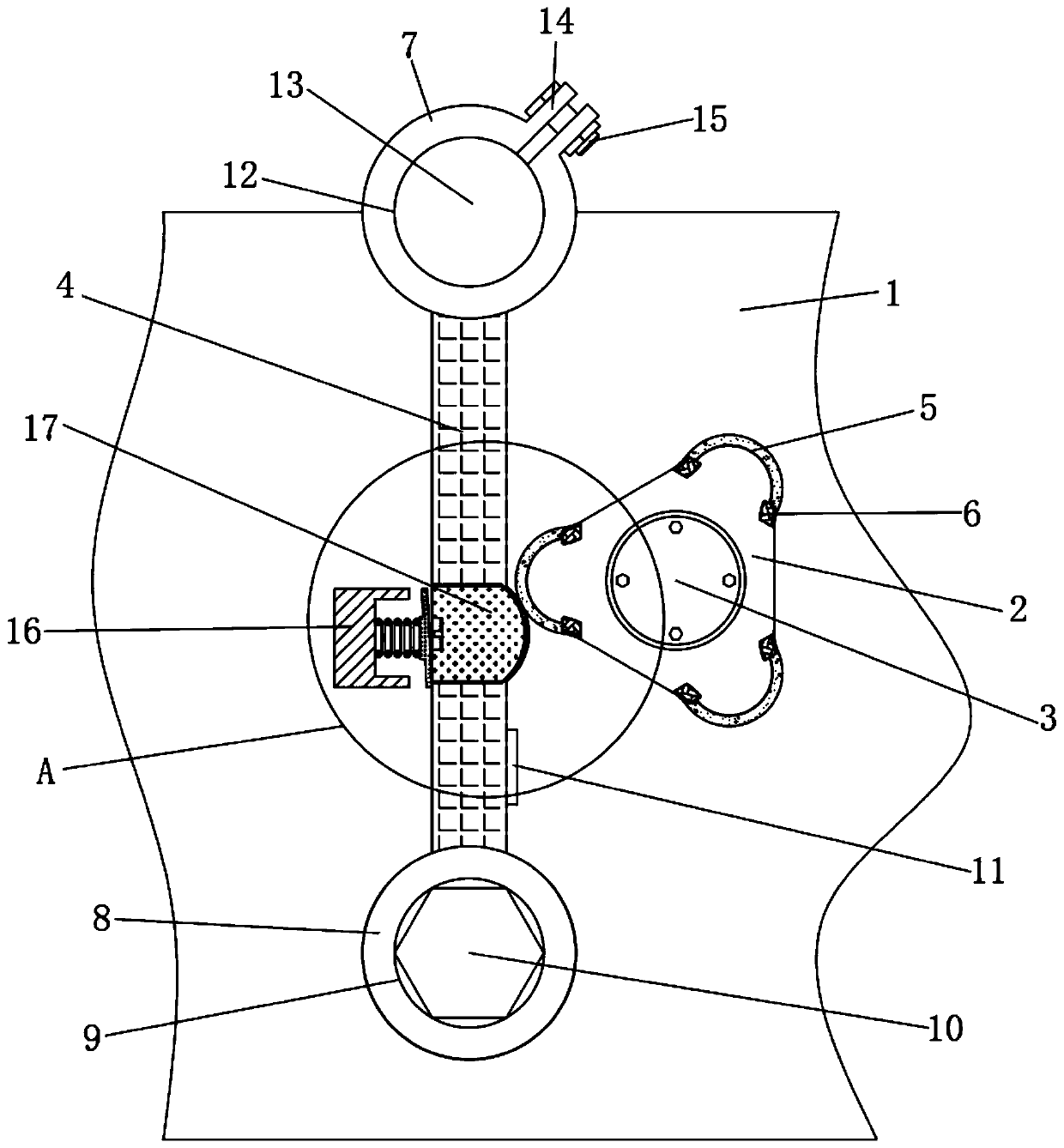
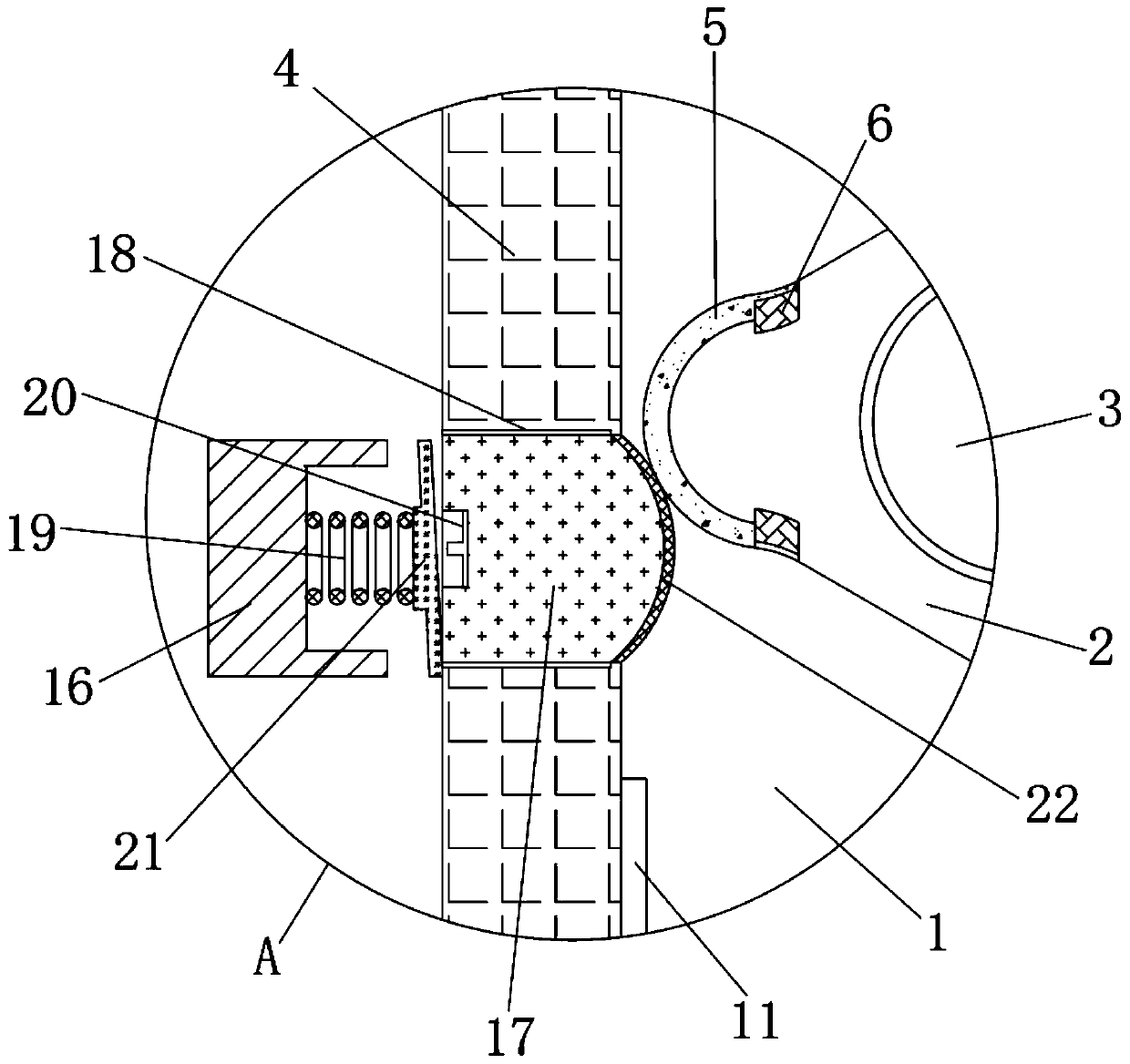
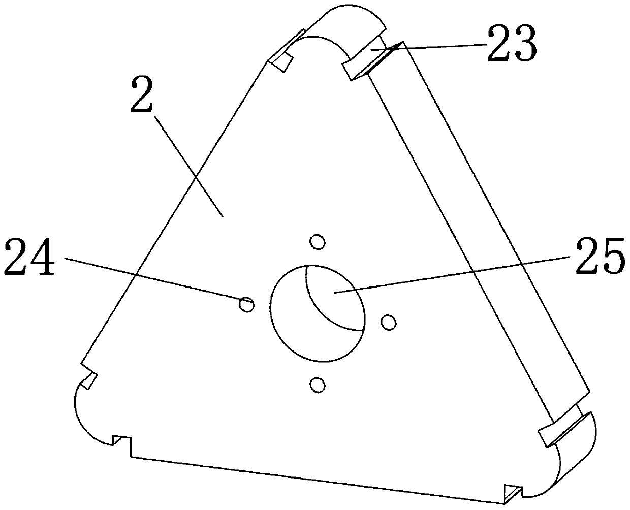
[0029] A warp protection buckle, comprising a cover plate 1, the front end of the cover plate 1 is rotatably inserted with a main shaft 3, the front end of the main shaft 3 is fixedly sleeved with a triangular cam 2, and the cam is designed as a triangular ellipse structure and installed on a roll On the cloth roll shaft, the cloth roll is used to rotate one circle, and ...


PUM


Abstract

The invention relates to the field of warp protection devices of textile machines, and specifically relates to a warp protection buckle. The warp protection buckle comprises a cover plate; a main rotating shaft is rotatably inserted in the front end face of the cover plate; the front end of the main rotating shaft is fixedly sleeved with a triangular cam; and a cam swing rod is vertically mountedon the left side of the triangular cam. The warp protection buckle provided by the invention has the following beneficial effects that the cam is designed into a triangular elliptical structure and ismounted on a cloth roller shaft; the cloth roller shaft rotates a circle and the cam pushes the cam swing rod, so that a warp protector is lifted up and down three times, so that a reed is uniformlyworn during operation, and the service life of the reed is prolonged; through the cooperation of a buffer strip and an extrusion protrusion, in the process of the arc surface contact conversion jump,buffering of extrusion impacts is realized, meanwhile, a limit plate and a spring are matched, and the rotation amplitude of the cam swing rod is limited; and by arranging the extrusion position as threaded connection, an extrusion block can be replaced conveniently, the maintenance cost is reduced, and the replacement and maintenance efficiency is improved.

Description

technical field [0001] The invention relates to the field of warp protection devices for textile machines, in particular to a warp protection buckle. Background technique [0002] The traditional textile machine warp protection device realizes the limitation and protection of the position of the warp through the rotation of the rotating shaft, thereby preventing the warp from crossing each other, providing an appropriate pre-tightening force for the warp, and making the textile machine run smoothly. [0003] However, due to the need for repeated pretensioning during the operation of the textile machine, it is easy to cause wear and tear on the rotating shaft and the protective device, reducing the service life. At the same time, due to uneven wear positions, the pretensioning effect on the warp yarns is not stable, which is easy to cause warp yarns. Breakage, and the rotation process is prone to jumps due to the extrusion between the plane and the arc surface, which in turn ...

Claims


Application Information

Patent Timeline
Patent Type & Authority Applications(China)
IPC IPC(8): D03D49/60D03D51/02D03D49/20
CPCD03D49/20D03D49/60D03D51/02
Inventor 邢桂松
Owner QINGDAO KAISHUO MACHINERY TECH CO LTD
Learn More