Pumping well under-pump injection agent mixing device

An injection agent and oil well pump technology, which is used in wellbore/well valve devices, wellbore/well components, and production fluids, etc., can solve problems such as waste of viscosity reducer, damage to special pumps, poor mixing effect, etc. The effect of improving oil pumping efficiency, improving utilization efficiency and less economic investment

Active Publication Date: 2020-06-05
山东赛纳石油科技有限公司
View PDF9 Cites 1 Cited by
  • Summary
  • Abstract
  • Description
  • Claims
  • Application Information

AI Technical Summary

Problems solved by technology

[0002] When pumping heavy oil wells, the friction between the heavy oil and the sucker rod makes it difficult for the sucker rod to go down, making it impossible to pump normally. One of the solutions to the difficulty of pumping such wells is to add a viscosity reducer into the casing. Reduce the viscosity of heavy oil, but because the viscosity reducer added from the casing cannot be fully mixed with the well fluid, the added viscosity reducer did not achieve the desired effect, and the problem of difficult oil pumping still cannot be solved
[0003] The current way of adding chemicals is generally to add a viscosity reducer into the oil casing, and use the free sedimentation of the viscosity reducer to mix with the oil. When this method is used, the mixing effect is not good, causing a large amount of viscosity reducer to be wasted. A powered impeller device is added between the pipelines inside the oil well. First, the pump is used to inject the agent into the pipeline. When the oil is brought into the pipeline from the bottom of the well, it is mixed under the action of the impeller. This device Although the mixing effect is improved, when in use, the power unit needs to be powered, which requires the laying of cables, and the space in the oil well is small, which makes the installation of the whole device more troublesome
[0004] When the agent is pumped into the casing, the amount of the agent must be ensured, but there will be a time gap when pumping oil, so it is necessary to make the special pump work at intervals, which will easily cause damage to the special pump for a long time, and then make the oilfield produce. lower work efficiency

Method used


Image

  • Pumping well under-pump injection agent mixing device
  • Pumping well under-pump injection agent mixing device
  • Pumping well under-pump injection agent mixing device

Examples


Embodiment Construction

[0018] The following will clearly and completely describe the technical solutions in the embodiments of the present invention with reference to the accompanying drawings in the embodiments of the present invention. Obviously, the described embodiments are only some, not all, embodiments of the present invention. Based on the embodiments of the present invention, all other embodiments obtained by persons of ordinary skill in the art without making creative efforts belong to the protection scope of the present invention. The drawings in the embodiments of the present invention: the different types of section lines in the drawings are not marked according to the national standard, and there is no requirement for the material of the components, but to distinguish the cross-sectional views of the components in the drawings.

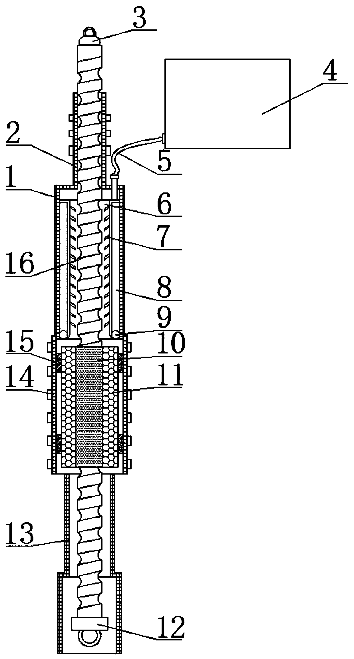
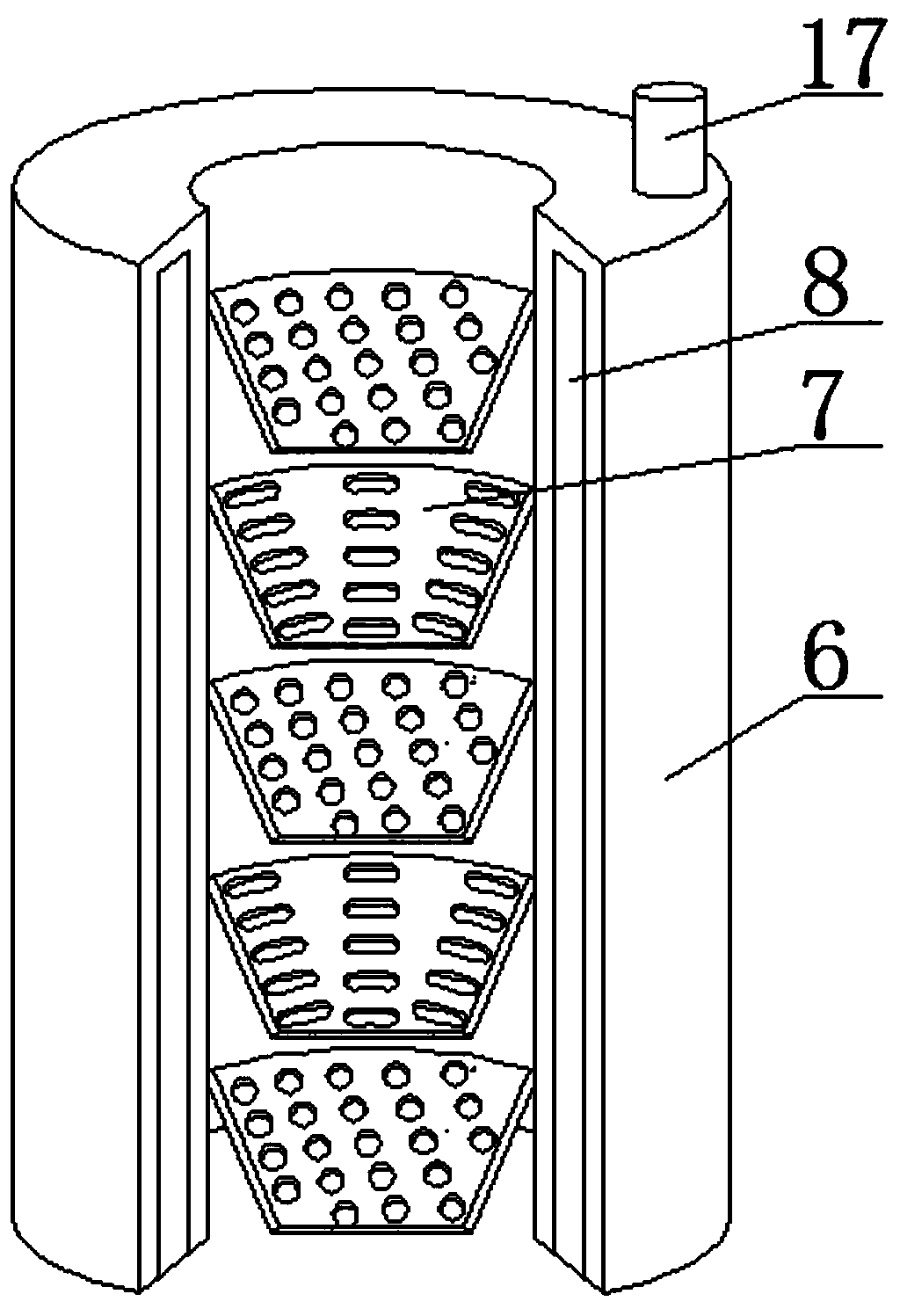
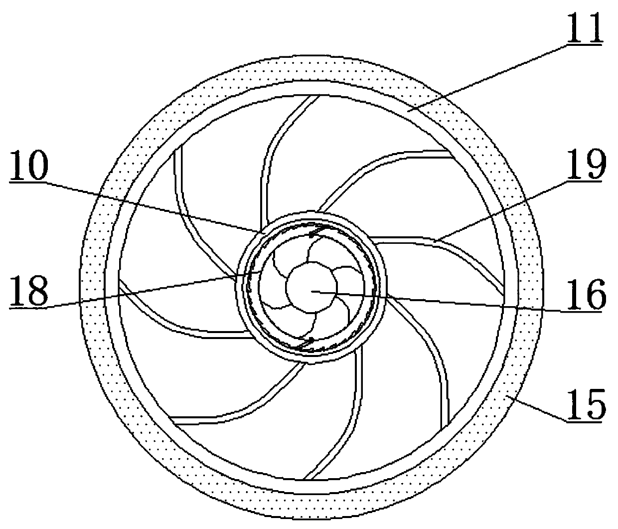
[0019] see Figure 1-3 , an injectant mixing device under the pump of an oil well, comprising a connecting casing 1 and an injectant storage device 4, the top...


PUM


Abstract

The invention relates to the technical field of oil well equipment, and discloses a pumping well under-pump injection agent mixing device. The device comprises a connecting sleeve pipe and an injection agent storage device; the top of the connecting sleeve pipe fixedly communicates with an upper connector, a screw is movably sleeved inside the upper connector, an upper hook is movably installed atone end, located above the upper connector, of the screw, and a fixed sleeve is movably sleeved inside the connecting sleeve pipe. According to the pumping well under-pump injection agent mixing device, by connecting the screw with a sucker rod, the screw, a flying gear and the connecting sleeve are matched, the screw is driven by the power of a pumping unit to move up and down, so that the flying gear drives an impeller device to rotate, so that the oil on the belt of the pumping unit is fully mixed with the medicament at the impeller device, the utilization efficiency of the medicament is improved, the installation of the device is simple, special power equipment is not needed, and the economic investment is low.

Description

technical field [0001] The invention relates to the technical field of oil well equipment, in particular to a pump injection agent mixing device for oil pumping wells. Background technique [0002] When pumping heavy oil wells, the friction between the heavy oil and the sucker rod makes it difficult for the sucker rod to go down, making it impossible to pump normally. One of the solutions to the difficulty of pumping such wells is to add a viscosity reducer into the casing. Viscosity reduction of heavy oil, but because the viscosity reducer added from the casing cannot be fully mixed with the well fluid, the added viscosity reducer did not achieve the desired effect, and the problem of difficult oil pumping still cannot be solved. [0003] The current way of adding chemicals is generally to add a viscosity reducer into the oil casing, and use the free sedimentation of the viscosity reducer to mix with the oil. When this method is used, the mixing effect is not good, causing ...

Claims


Application Information

Patent Timeline
Patent Type & Authority Applications(China)
IPC IPC(8): E21B43/22E21B34/08
CPCE21B34/08E21B43/16
Inventor 不公告发明人
Owner 山东赛纳石油科技有限公司
Why Eureka
Try Eureka