a ball valve

A ball valve and valve seat technology, applied in the field of ball valves with ash removal function, can solve the problems of ball valve leakage, scratches, damaged valve balls, etc., and achieve the effects of ensuring air tightness, reducing economic losses, and high degree of automation

Active Publication Date: 2021-08-10
君品集团有限公司
View PDF0 Cites 0 Cited by
  • Summary
  • Abstract
  • Description
  • Claims
  • Application Information

AI Technical Summary

Problems solved by technology

[0003] In order to solve the problem that the dust particles in the existing gas pipeline network will scratch and damage the valve ball and cause the ball valve to leak, the present invention proposes a ball valve with ash removal function

Method used


Image

  • a ball valve
  • a ball valve
  • a ball valve

Examples


Embodiment 1

[0029] Embodiment one: see Figure 1 to Figure 8

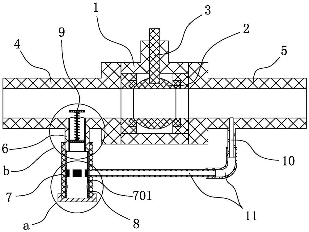
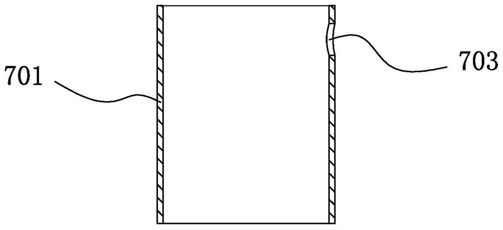
[0030] A ball valve, comprising a valve seat 1, a valve ball 2 arranged in the valve seat 1, a valve stem 3 used to drive the valve ball 2, an intake pipe 4 arranged on one side of the valve seat 1, and an air intake pipe 4 arranged on the other side of the valve seat 1 One side of the air outlet connecting pipe 5, the outer wall of the air inlet connecting pipe 4 is provided with an ash falling pipe 6, the ash falling pipe 6 is erected on the lower side of the air inlet connecting pipe 4, and the upper end of the ash falling pipe 6 is connected with the air inlet connecting pipe 4 And connected, the central axis of the ash-falling pipe 6 is perpendicular to the central axis of the intake pipe 4 , and a first sliding pipe 601 is embedded in the tube hole of the ash-falling pipe 6 .

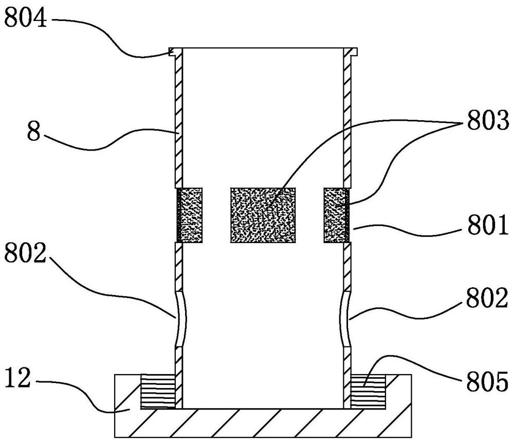
[0031] The lower end of the ash fall pipe 6 is provided with an ash storage pipe 7, the upper section of the ash storage pipe 7 is sleeved on th...

Embodiment 2

[0043] Embodiment two: see Figure 9 to Figure 12

[0044] A ball valve, comprising a valve seat 1, a valve ball 2 arranged in the valve seat 1, a valve stem 3 used to drive the valve ball 2, an intake pipe 4 arranged on one side of the valve seat 1, and an air intake pipe 4 arranged on the other side of the valve seat 1 One side of the air outlet connecting pipe 5, the outer wall of the air inlet connecting pipe 4 is provided with an ash falling pipe 6, the ash falling pipe 6 is erected on the lower side of the air inlet connecting pipe 4, and the upper end of the ash falling pipe 6 is connected with the air inlet connecting pipe 4 And connected, the central axis of the ash-falling pipe 6 is perpendicular to the central axis of the intake pipe 4 , and a first sliding pipe 601 is embedded in the tube hole of the ash-falling pipe 6 .

[0045] The lower end of the ash fall pipe 6 is provided with an ash storage pipe 7, the upper section of the ash storage pipe 7 is sleeved on t...


PUM


Abstract

The invention discloses a ball valve, which relates to the technical field of ball valves, and comprises a valve seat, a valve ball arranged in the valve seat, a valve stem used to drive the valve ball, an intake pipe arranged on one side of the valve seat, and a valve rod arranged in the valve seat. On the other side of the air outlet pipe, the outer wall of the air intake pipe is provided with an ash discharge pipe, the pipe hole of the ash discharge pipe is embedded with a first sliding pipe, and the lower end of the ash discharge pipe is provided with an ash storage pipe, located under the ash discharge pipe A second sliding pipe is embedded in the tube hole of the ash storage pipe on the side, a first air vent is opened on the pipe wall of the ash storage pipe, a second air vent is opened on the pipe wall of the second sliding pipe, the first air vent is connected with the The position of the second air outlet corresponds to and communicates with. A release pipe is provided on the outer wall of the air outlet connecting pipe. One end of the air outlet pipe is connected and communicated with the air outlet connecting pipe, and the other end is connected and communicated with the first air outlet on the ash storage pipe through several pipe fittings. In order to solve the problem that the dust particles in the existing gas pipeline network will scratch and damage the valve ball and cause the ball valve to leak, the present invention proposes a ball valve with ash removal function.

Description

technical field [0001] The invention relates to the technical field of ball valves, in particular to a ball valve with ash removal function. Background technique [0002] The ball valve here mainly refers to the polyethylene ball valve, which is a plastic ball valve and is mainly used for natural gas transportation in the gas pipeline network. The ball valve has the advantages of convenient installation and strong corrosion resistance. However, due to the characteristics of plastic, the valve ball of this ball valve is easily scratched and damaged by dust particles in the transport medium, which affects the overall airtightness of the ball valve. Contents of the invention [0003] In order to solve the problem that the dust particles in the existing gas pipeline network will scratch and damage the valve ball and cause the ball valve to leak, the present invention proposes a ball valve with ash removal function. [0004] In order to achieve the above object, the present in...

Claims


Application Information

Patent Timeline
Patent Type & Authority Patents(China)
IPC IPC(8): F16K5/06F16K5/08F16K27/06
CPCF16K5/06F16K5/08F16K27/06
Inventor 汤裕浩汪荣浩王铁军
Owner 君品集团有限公司
Why Eureka
Try Eureka