
Three-dimensional scanning path planning method and device

A three-dimensional scanning and path planning technology, applied in the field of three-dimensional scanning, can solve the problems of teaching path differences, increased operating costs, restrictions, etc., to achieve the effect of reducing the number of times, high precision, automatic scanning, and accurate data

Active Publication Date: 2020-06-05
TENYOUN 3D(TIANJIN)TECH CO LTD
View PDF18 Cites 5 Cited by
  • Summary
  • Abstract
  • Description
  • Claims
  • Application Information

AI Technical Summary

Problems solved by technology

[0003] With the promotion of robotic automated 3D scanning technology, the working mode of gradually teaching the 3D scanning path based on the engineer's personal experience can no longer meet the rapidly growing user measurement needs.
First of all, the personal experience of engineers limits their ability to deal with different types of workpieces, and the differences in experience among different engineers will also lead to differences in teaching paths, which in turn affect measurement efficiency and even measurement accuracy; secondly, for a large number of measured workpieces or For users with high update frequency of measurement requirements, it is unacceptable to spend a lot of time and cost in the iterative process of manual teaching; finally, for suppliers that provide 3D inspection services, it is necessary to meet the growing needs of users through manual teaching. measurement needs, it is necessary to maintain a large-scale team of experienced engineers, which also means an increase in operating costs

Method used


Image

  • Three-dimensional scanning path planning method and device
  • Three-dimensional scanning path planning method and device
  • Three-dimensional scanning path planning method and device

Examples


Embodiment Construction

[0034] In order to more clearly understand the above objects, features and advantages of the present invention, the present invention will be further described in detail below in conjunction with the accompanying drawings and embodiments. It should be understood that the described embodiments are some, not all, embodiments of the present invention. The specific embodiments described here are only used to explain the present invention, but not to limit the present invention. All other embodiments obtained by those skilled in the art based on the described embodiments of the present invention belong to the protection scope of the present invention.

[0035] It should be noted that in this article, relative terms such as "first" and "second" are only used to distinguish one entity or operation from another entity or operation, and do not necessarily require or imply these No such actual relationship or order exists between entities or operations.

[0036] First aspect, such as ...


PUM


Abstract

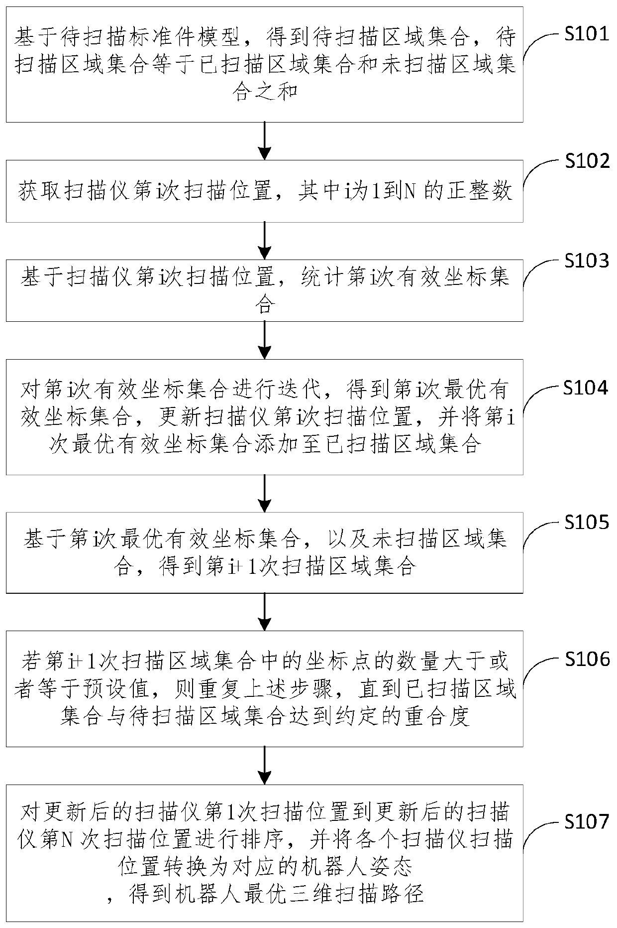
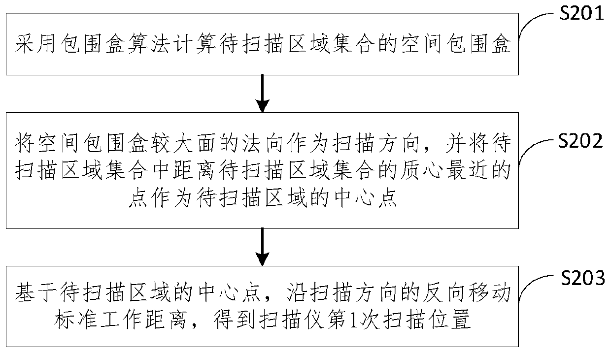
The invention relates to a three-dimensional scanning path planning method and device, and belongs to the technical field of three-dimensional scanning. The method comprises the steps: calculating theith scanning position of a scanner based on a to-be-scanned area set; determining an ith optimal effective coordinate set according to the ith scanning position of the scanner; and calculating an (i+ 1) th scanning area set based on the ith optimal effective coordinate set, and repeating the previous steps when the number of the coordinate points in the (i + 1) th scanning area set is greater than or equal to a preset value. A plurality of scanning positions can be determined through multiple cycle steps, the scanned area set continuously grows, the area set to be scanned reaches the agreedoverlap ratio, the final scanning positions from the first scanning position of the scanner to the Nth scanning position of the scanner are ranked, all the scanning positions are converted into the corresponding robot postures, the optimal three-dimensional scanning path is obtained, and thus high-efficiency, high-precision and automatic scanning of the robot is achieved.

Description

technical field [0001] The invention relates to the technical field of three-dimensional scanning, in particular to a method and device for planning a three-dimensional scanning path. Background technique [0002] Robot automated 3D scanning is a technology that uses a robot and a 3D scanner to perform non-contact measurement of the surface data of the measured object. In order to meet the size, shape and measurement requirements of different measured workpieces, the robot often needs to adopt different shooting paths. The traditional shooting path planning work is usually completed by the teaching engineer relying on personal experience. When the engineer receives the measurement requirements of the DUT and the user, he manually controls the robot to move to a certain estimated scanning position, and then performs the actual scanning. According to the scanning The results are used to judge whether the current location meets the measurement requirements. If it is not satisfi...

Claims


Application Information

Patent Timeline
Patent Type & Authority Applications(China)
IPC IPC(8): G01B11/00G01B11/24
CPCG01B11/002G01B11/24
Inventor 牛涛张翔宇李仁举
Owner TENYOUN 3D(TIANJIN)TECH CO LTD
Learn More