Check patentability & draft patents in minutes with Patsnap Eureka AI!

Electronic lock for casework sliding doors

A technology of sled and lock assembly is applied in the field of cabinets, which can solve the problems of insufficient safety and obstructing sight.

Active Publication Date: 2020-06-05
雅固拉国际有限公司
View PDF6 Cites 2 Cited by
  • Summary
  • Abstract
  • Description
  • Claims
  • Application Information

AI Technical Summary

Problems solved by technology

Traditional mechanical key lock devices and other devices may be inadequate in terms of security and / or need to be positioned in such a way that obstructs the customer's view of the items displayed in the glass display case

Method used


Image

  • Electronic lock for casework sliding doors
  • Electronic lock for casework sliding doors
  • Electronic lock for casework sliding doors

Examples


Embodiment Construction

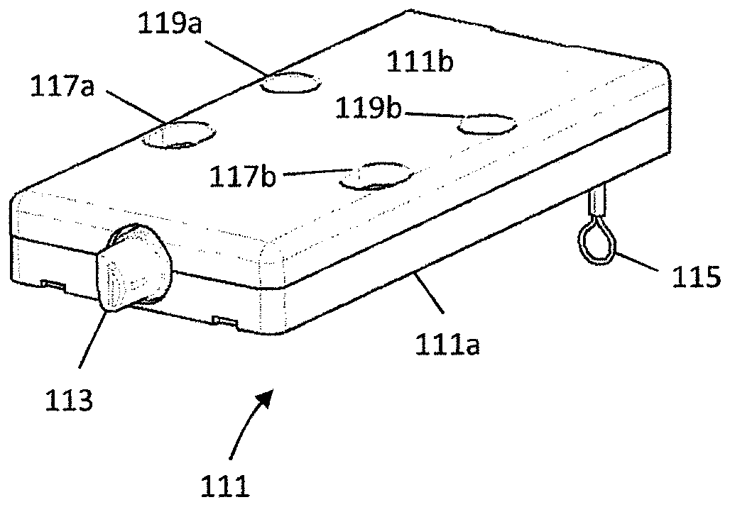
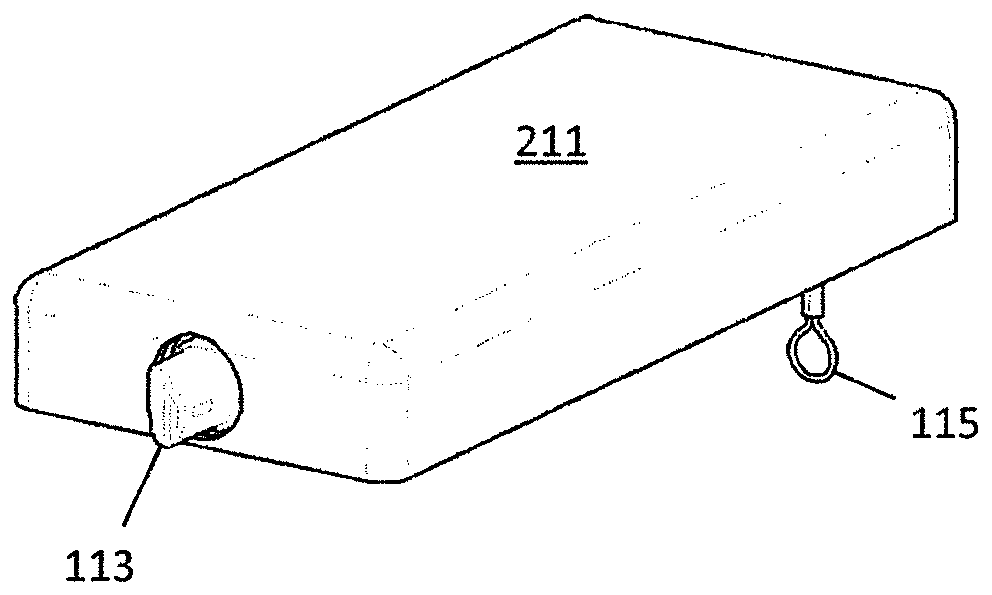
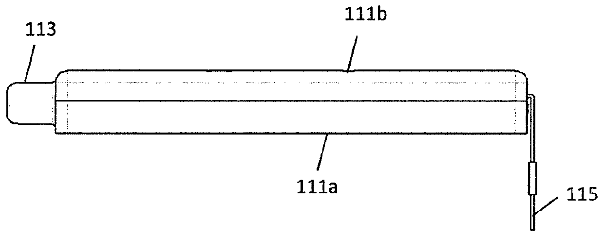
[0039] figure 1 is an isometric view of a lock assembly according to an embodiment of the invention. The lock assembly includes a housing 111 with a bolt 113 shown extending from an aperture in one side of the housing. Bolts are usually passed through the motor ( figure 1 not shown in ) to extend or retract from the housing into the housing.

[0040] exist figure 1 In an embodiment, the housing is substantially parallelepiped-shaped. The housing is formed by a bottom 111a or base and a top 111b or lid, wherein the bottom and top are removable from each other in order to provide access to the contents of the housing. exist figure 1 In an embodiment, the orifice is formed on one side of the housing, with part of the hole being at the bottom of the housing and part of the hole being at the top of the housing.

[0041] The mounting holes are visible on the top of the case. The mounting holes can be used with screws, for example to mount the housing into a cabinet. The moun...


PUM


Abstract

An electronic locking device to secure linear transitioning or sliding doors. The device design allows for an electronic access point such as an electronic keypad or RFID reader when presented with anapproved access code to electronically activate the device and provide for unlocking and relocking. The design also allows for lock status feedback and for automatic relocking of the sliding door when the lock pin is in the extended position and the door is closed.

Description

Background technique [0001] The present invention relates generally to the field of cabinetry and, more particularly, to an electronic latching and locking system for securing linear transition (sliding) doors. [0002] Retail display cases are usually stationary. Conventional mechanical key lock devices and other devices may be insufficient in security and / or need to be positioned in such a way that it obstructs a customer's view of the items displayed in the glass display case. Contents of the invention [0003] In some embodiments, the lock includes a bolt driven by a motor between a locked or extended position and an unlocked or retracted position. In some embodiments, the bolt is coupled to a sled that is moved by the motor between a forward position (putting the bolt in the locked position) and a rearward position (putting the bolt in the unlocked position). position) between. In some embodiments, a motor drives a drive screw to move the sled. In some embodiments, ...

Claims


Application Information

Patent Timeline
Patent Type & Authority Applications(China)
IPC IPC(8): E05B65/08E05B47/00E05B65/44E05B17/06G07C9/00
CPCG07C9/00944G07C2009/00634G07C9/00896E05B2047/0023E05B2047/0094E05B2047/0068E05B2047/0069E05B2047/0065E05B47/0012E05B47/026E05B63/0052E05B65/0864E05B63/044E05C19/028E05C1/085E05B65/44E05Y2201/434E05Y2900/202E05Y2400/32E05Y2201/422
Inventor C·米利根T·瓦塔纳贝
Owner 雅固拉国际有限公司
Features
  • R&D
  • Intellectual Property
  • Life Sciences
  • Materials
  • Tech Scout
  • Unparalleled Data Quality
  • Higher Quality Content
  • 60% Fewer Hallucinations
Learn More