Central gas collecting pipe of shift converter

The technology of a shift furnace and a gas collecting pipe is applied in the field of shift furnace, which can solve the problems of high exhaust gas composition, insufficient reaction of process gas, influence on the quality index of product gas, etc., and achieve the effect of improving quality

Pending Publication Date: 2020-06-09
JIANGSU PUGE MACHINERY
View PDF0 Cites 1 Cited by
  • Summary
  • Abstract
  • Description
  • Claims
  • Application Information

AI Technical Summary

Problems solved by technology

[0003] Since the process gas enters the central gas collecting pipe and exits the shift furnace after only one catalytic reaction, part of the process

Method used


Image

  • Central gas collecting pipe of shift converter

Examples


Embodiment Construction

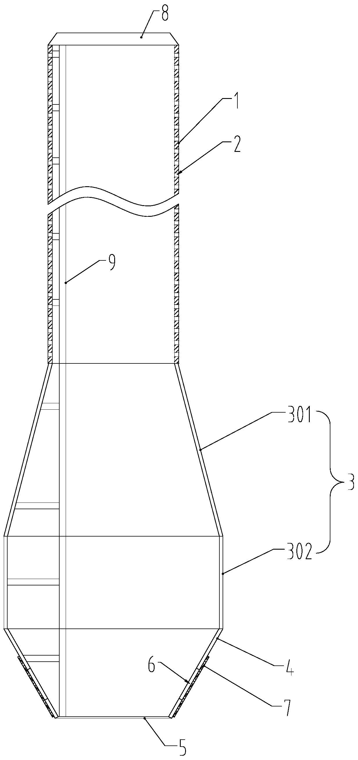
[0018] Specific embodiments of the present invention will be described in detail below in conjunction with the accompanying drawings.

[0019] like figure 1 As shown, the central gas collecting pipe of the converter includes a pipe body 1, which is covered with air inlet holes 2, and the lower end of the pipe body 1 is connected with an expansion pipe 3 whose diameter is larger than that of the pipe body 1, and the lower end of the expansion pipe 3 is connected to Air distribution pipe 4 is arranged, and the lower end of air distribution pipe 4 is closed by base plate 5, and a large amount of air outlet holes 6 are evenly distributed on the pipe wall of air distribution pipe 4.

[0020] The expansion tube 3 includes a cone body 301, the diameter of the cone body 301 gradually expands from top to bottom, the lower end of the cone body 301 is connected with a straight body 302 whose diameter is larger than that of the pipe body 1, and the air distribution pipe 4 is connected to ...


PUM


Abstract

The invention relates to a central gas collecting pipe of a shift converter. The central gas collecting pipe comprises a pipe body, wherein gas inlet holes are fully distributed in the pipe body; thelower end of the pipe body is connected with an expansion pipe with a diameter larger than the diameter of the pipe body; the lower end of the expansion pipe is connected with a gas distributing pipe;the lower end of the gas distributing pipe is sealed by a bottom plate; and a large number of gas outlet holes are evenly distributed in the wall of the gas distributing pipe. The central gas collecting pipe can guide finished gas to enter a catalyst layer again for a secondary reaction so as to improve the quality of the finished gas.

Description

Technical field: [0001] The invention belongs to the technical field of converter furnaces, and in particular relates to a central gas collecting pipe of a converter furnace. Background technique: [0002] The shift furnace can introduce the process gas into the catalyst for chemical reaction, and then generate the product gas, and the central gas collecting pipe is a device for collecting the product gas. The central gas collecting pipe is installed inside the converter shell, and the outside of the central gas collecting pipe is the catalyst. , the interior is hollow and communicates with the product gas outlet provided on the shell of the shift furnace. The process gas passes through the catalyst layer and enters the central gas collecting pipe, and then exits the shift furnace. [0003] Since the process gas enters the central gas collecting pipe and exits the shift furnace after only one catalytic reaction, part of the process gas reacts insufficiently, resulting in hig...

Claims


Application Information

Patent Timeline
IPC IPC(8): B01J8/02
CPCB01J8/02B01J8/0278
Inventor 阮建飞黄和芳
Owner JIANGSU PUGE MACHINERY
Why Eureka
Try Eureka