Bolt screw-in machine

A technology of screwing and screwing, applied in metal processing, metal processing equipment, manufacturing tools, etc., can solve problems such as low screwing efficiency

Pending Publication Date: 2020-06-09
SHENZHEN HAIPENGXIN ELECTRONICS
View PDF0 Cites 0 Cited by
  • Summary
  • Abstract
  • Description
  • Claims
  • Application Information

AI Technical Summary

Problems solved by technology

[0004] The purpose of the present invention is to provide a screw screwing machine, aiming to solve the problem of low efficiency of screw screwing in the prior art

Method used


Image

  • Bolt screw-in machine
  • Bolt screw-in machine
  • Bolt screw-in machine

Examples


Embodiment approach

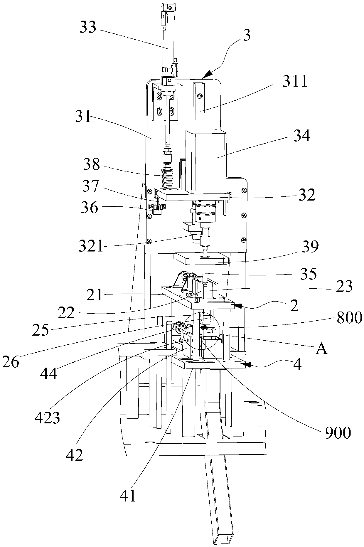
[0039] Further, see Figure 5 , as a specific embodiment of the screw screwing machine provided by the present invention, the screw-in lifting drive mechanism 33 is a screw-in lifting cylinder located on the screw-in mounting plate 31, and the piston rod of the screw-in lifting cylinder is screwed into the lifting plate 32. A buffer spring 38 is screwed in therebetween to avoid the rigid impact of the bit 35 and the screw 800 .

specific Embodiment approach

[0040] Further, see Figure 5 , as a specific embodiment of the screw screwing machine provided by the present invention, the screw-in installation plate 31 is provided with a screw-in guide plate 39, and the screw-in guide plate 39 is located at the screw-in lifting plate 32 away from the screw-in lifting drive mechanism 33. On one side, the screw-in guide plate 39 is provided with a screw-in relief hole for the bit 35 to pass through. The bit 35 is screwed into the relief hole to screw the screw 800 in, so as to ensure that the bit 35 with a certain length will not deviate when used.

[0041] Further, see Figure 5 , as a specific embodiment of the screw screwing machine provided by the present invention, the screw-in lifting plate 32 is provided with an oil pressure buffer 321, and the oil pressure buffer 321 is located on a side of the screw-in lifting plate 32 close to the screw-in guide plate 39. side. The oil pressure buffer 321 and the screw-in position sensor 36 ca...


PUM


Abstract

The invention discloses a bolt screw-in machine. The bolt screw-in machine comprises a discharge mechanism, a feeding mechanism and a screw-in assembly, wherein the screw-in assembly comprises a screw-in mounting plate, a screw-in lifting plate, a screw-in lifting drive mechanism, a screw-in drive motor, a screwdriver bit, a screw-in position sensor and a screw-in trigger piece, wherein the discharge mechanism comprises a discharge bottom plate and a discharge placing plate; a wiring frame of a to-be-screwed-in bolt is placed on the discharge mechanism; the feeding mechanism is used for feeding a bolt to a position below the screwdriver bit; the screw-in assembly is used for screwing in the bolt on the feeding mechanism into the wiring frame of the to-be-screwed-in bolt on the discharge mechanism; the screw-in lifting drive mechanism drives the screw-in lifting plate to move downwards, so that the screwdriver bit is in contact with the bolt on the feeding mechanism, and the screw-in drive motor drives the screwdriver bit to perform screw-in operation on the bolt; and while the screw-in trigger piece on the screw-in lifting plate triggers the screw-in position sensor, the screw-in drive motor stops rotation, so that the bolt is screwed into preset depth, and therefore, screw-in efficiency is improved.

Description

technical field [0001] The invention relates to the field of wiring frame processing equipment, in particular to a screw screwing machine. Background technique [0002] The wiring frame is used for the installation and fixing of the wires. Usually, the wires are fixed on the wiring frame with screws. Therefore, in order to facilitate the subsequent installation and fixing, the screws need to be screwed into the wiring frame in advance, and the subsequent operation of the screws can complete the installation and fixing of the wires. [0003] The existing screw-in equipment is mainly to directly screw the screw to the bottom of the terminal frame, and the screw-in height cannot be adjusted, or the height of the screw to be screwed into the terminal frame can be adjusted by screwing in the bottom and then reversed to fix the number of turns. low efficiency. Contents of the invention [0004] The object of the present invention is to provide a screw driving machine, aiming to...

Claims


Application Information

Patent Timeline
Patent Type & Authority Applications(China)
IPC IPC(8): B23P19/06
CPCB23P19/001B23P19/06
Inventor 刘辉翔陈进李叶来谢述红陈清
Owner SHENZHEN HAIPENGXIN ELECTRONICS
Why Eureka
Try Eureka