Extraction roller

A technology for fastening elements, bases, applied in the field of pick-up rollers, which can solve problems such as wear marks that cannot be easily handled, impossible to replace, etc.

Active Publication Date: 2020-06-09
MASCHINENFABRIK RIETER AG
View PDF6 Cites 0 Cited by
  • Summary
  • Abstract
  • Description
  • Claims
  • Application Information

AI Technical Summary

Problems solved by technology

However, such wear marks cannot be dealt with easily, as it is not p

Method used


Image

  • Extraction roller
  • Extraction roller
  • Extraction roller

Examples


Embodiment Construction

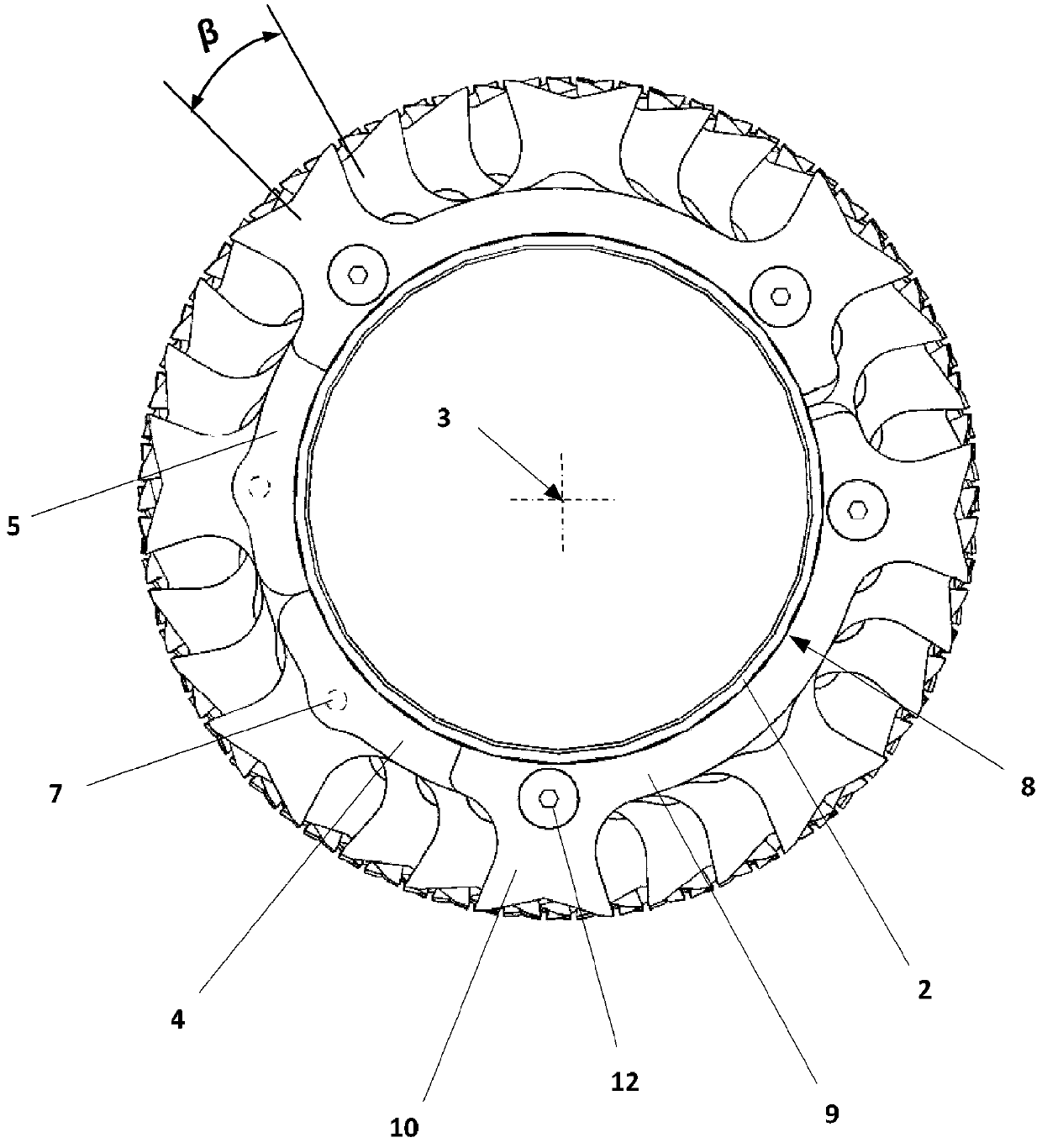
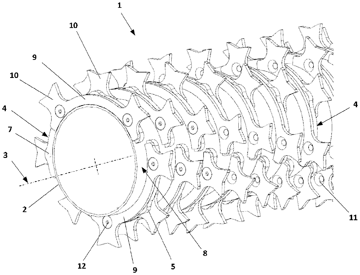
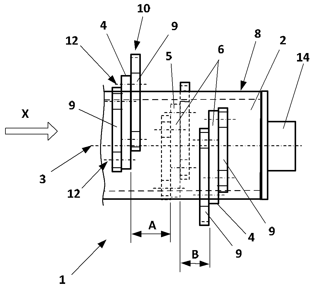
[0029] figure 1 A schematic perspective representation of the extraction roller 1 is shown. The extraction roll 1 has a roll axis 3 and comprises a base body 2 on a surface 8 of which a series of a plurality of first fastening elements 4 and second fastening elements 5 is arranged in one plane and in in concentric adjacent planes. Two sets of toothed elements 9 are respectively mounted on the fastening elements 4 and 5 via screws 12 , wherein the screws 12 engage in through-openings 11 formed in the toothed elements 9 and via through-openings 7 designed as female threads in the fastening elements 4 and 5 . fastening element 4 or 5. Two sets of tooth elements 9 are mounted on the fastening elements 4 and 5, respectively. Each tooth element 9 is equipped with two teeth 10 . The fastening elements 4 and 5 and thus also the tooth elements 9 are arranged in a sequentially offset manner in the direction of the roller axis 3 in the circumferential direction. Since all tooth elem...


PUM


Abstract

The invention relates to an extraction roller (1) for mechanically opening fiber bales, having a base body (2) designed as a tube, a roller axis (3), and fastening elements (4, 5) situated on the basebody (2) along the roller axis (3). The fastening elements (4) protrude perpendicularly from a surface (6) [sic; (8)] of the base body (2), and each fastening element (4) has at least one through opening (7), parallel to the roller axis (3), for fastening tooth elements (9). Two tooth elements (9) in each case, having at least two teeth (10) in each case, are mounted on each fastening element (4). The two tooth elements (9) are situated at the particular fastening element (4) on opposite sides thereof. The tooth elements (9) are arranged in a circumferential direction of the base body (2) insuch a way that the teeth (10) of the respective tooth elements (9) fastened to a fastening element (4) are offset relative to one another in the circumferential direction.

Description

technical field [0001] The invention relates to an extraction roll for mechanically opening fiber bales. Background technique [0002] Take-off rolls are used in so-called bale take-off machines or bale openers to extract fibers or fiber batts from pressed fiber bales. To do this, one or more extraction rolls are moved across the fiber bale. Bale openers are also known from the prior art, in which the fiber bales are moved past stationary extraction rollers. [0003] Such extraction rolls are equipped with teeth which engage in the fiber bale and tear or tear fibers or fiber batts out of the fiber bale due to the rotation of the extraction roll. The bale unloader is positioned at the start of the processing line in the spinning preparation machine (blow room) for processing fiber material (e.g. cotton or synthetic fibers or mixtures thereof) and the sequence is aligned within the spinning preparation machine The continuity of (sequences) has a decisive influence. In the ...

Claims


Application Information

Patent Timeline
IPC IPC(8): D01G7/06
CPCD01G7/04B02C18/184D01G7/06
Inventor L.布劳恩
Owner MASCHINENFABRIK RIETER AG
Why Eureka
Try Eureka