Hydraulic brake stator and hydraulic brake

A brake stator and stator technology, applied in the direction of liquid resistance brakes, brake types, mechanical equipment, etc., can solve the problems of large oil filling and discharging resistance, unsuitable for high-speed vehicles, long braking response time, etc., to improve safety and weight Lightweight, strong braking effect

Pending Publication Date: 2020-06-09
CRRC DALIAN INST CO LTD
View PDF0 Cites 1 Cited by
  • Summary
  • Abstract
  • Description
  • Claims
  • Application Information

AI Technical Summary

Problems solved by technology

[0013] As an auxiliary braking method for locomotives, hydraulic braking has significant advantages. However, the existing hydraulic braking

Method used


Image

  • Hydraulic brake stator and hydraulic brake
  • Hydraulic brake stator and hydraulic brake
  • Hydraulic brake stator and hydraulic brake

Examples


Embodiment Construction

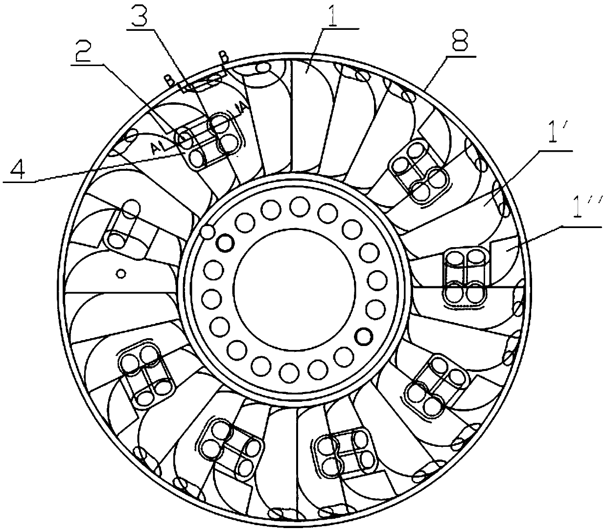
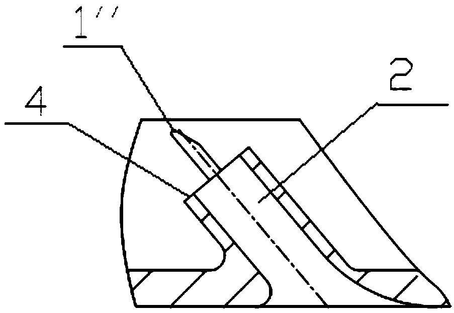
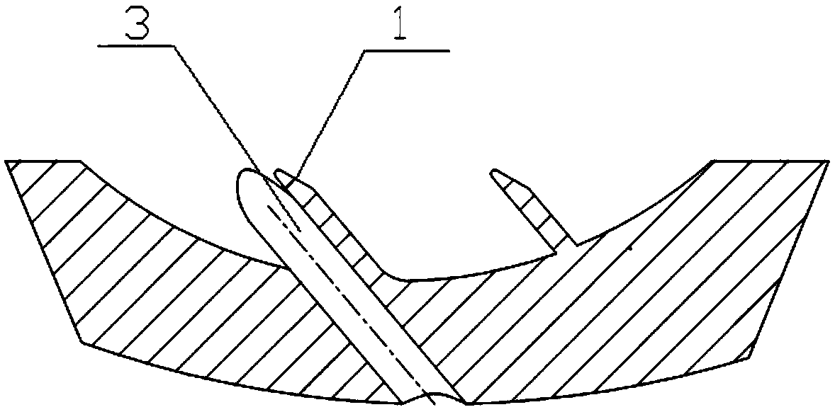
[0031] Such as Figure 1 to Figure 3 As shown, a hydraulic brake stator 8 includes a stator body and a plurality of stator vanes 1 arranged on the stator body, and the stator is provided with an oil inlet hole 2 and an oil discharge hole 3, and the oil inlet hole 2 is from The back side of the stator extends to the front side of the stator through the inside of the stator blade 1, and the oil discharge hole 3 is arranged at the edge of the stator.

[0032] A plurality of stator blades 1 are divided into conventional blades 1' and oil inlet blades 1", the oil inlet holes 2 pass through the inside of the oil inlet blades 1", and the oil inlet blades 1" are provided with the thickness of the part of the oil inlet holes 2 Thickness greater than conventional blades 1'. In this embodiment, a plurality of oil inlet blades 1" are circumferentially distributed on the stator, and two or more conventional blades 1' are arranged between adjacent oil inlet blades 1".

[0033] The middle p...


PUM

PropertyMeasurementUnit
Slopeaaaaaaaaaa

Abstract

The invention discloses a hydraulic brake stator and a hydraulic brake. The hydraulic brake stator comprises a stator body and a plurality of stator blades arranged on the stator body, wherein an oilinlet hole and an oil drainage hole are formed in the stator; the oil inlet hole extends to the front surface of the stator from the back surface of the stator through the interiors of the stator blades; and the oil drainage hole is formed in the edge of the stator. The hydraulic brake stator and the hydraulic brake are capable of realizing rapid oil filling and oil drainage, high in braking response speed, and applicable to a high-speed vehicle; the brake is small, light in weight, and convenient to install; the brake is applicable to long-time continuous braking, and free from mechanical wear; the brake improves the safety of downhill running, and can realize a constant low speed during downhill; and the brake is low in noise, and high in continuous braking capacity.

Description

technical field [0001] The invention relates to a hydraulic brake device, in particular to a hydraulic brake stator and a hydraulic brake. Background technique [0002] Locomotives running in mountainous areas need to use brake shoes frequently in order to control the speed when going downhill. Long-term use will cause serious wear of the brake shoes and generate a lot of heat, which is very detrimental to the safe running of the rolling stock. In order to ensure For good braking performance, in addition to brake shoe braking, rolling stock also needs to be equipped with auxiliary braking methods. [0003] In addition to the need to equip the locomotive with an auxiliary braking method, for the sake of safety, the locomotive running downhill is required to be able to adjust the speed of the locomotive or maintain a constant low speed downhill, that is, the braking power can be adjusted steplessly according to the speed of the vehicle. [0004] At present, the commonly used ...

Claims


Application Information

Patent Timeline
IPC IPC(8): F16D57/02
CPCF16D57/02
Inventor 庞洁曹晓龙欧名毫刘洪坤高恩芹
Owner CRRC DALIAN INST CO LTD
Why Eureka
Try Eureka