Burner cap used for gas stove

A gas stove and fire cover technology, which is applied to the transportation of non-flammable liquid/gas, burners, and combustion methods. Flame performance, applicability enhancement, effect of improving mixing uniformity

Active Publication Date: 2020-06-09
NINGBO FOTILE KITCHEN WARE CO LTD
View PDF9 Cites 1 Cited by
  • Summary
  • Abstract
  • Description
  • Claims
  • Application Information

AI Technical Summary

Problems solved by technology

[0002] At present, most of the traditional burner fire caps sold on the market are milled with one groove, that is, a fire pilot groove is milled on the top of the fire cap body. Disconnected, so it is easy to cause deformation of the fire cover body, thus affecting the ignition effect
For example, the Chinese invention patent "Gas burner with fire transmission device and flameout protection function" whose patent number is 201220464214.0 (notification number is CN202813375U) discloses a similar fire transmission structure. ring fire hole, and the outer ring fire transmission device is also provided on the outer ring fire spray right, the outer ring fire transmission device is a boss installed on the inner wall of the outer ring fire spray ring The outer ring fire transmission hole and the outer ring fire transmission groove on the platform and the outer ring fire spraying ring are composed of the outer ring fire transmission hole and the outer ring fire transmission groove, and the outer ring fire transmission hole and the outer ring fire transmission groove are connected with a The flame-spray holes of the outer ring are connected to realize rapid fire transmission; the fire-transfer channel of this fire-transfer structure is open, and the fire transmission is linear, that is, the fire-transfer channel is exposed on the surface of the outer ring fire cover. This design has a The advantage is that the supply of secondary air in the fire transfer tank is sufficient, and the open fire transfer tank can ensure the supply of secondary air when the flame burns in the fire transfer tank, which is conducive to flame combustion and fire transmission, and has the characteristics of fast fire transmission. However, the open fire transfer tank has two disadvantages. First, the open fire transfer tank is easy to cause blockage of the fire transfer tank. Fire performance, which is also the main reason for the blockage and maintenance of the current fire transmission tank; second, the open fire transmission tank has high requirements on the damper of the stove, because when the damper is opened, too much air at one time will cause the airflow velocity to be too high, resulting in When burning, it is away from the flame or out of fire. Therefore, the structural characteristics of the open fire transfer groove are poor flame stability characteristics. Therefore, to ensure the fire transfer performance of the open fire transfer groove, the damper is basically closed very small, but the damper Turning it down is not conducive to the combustion efficiency of the stove, and it is also not conducive to the emission of smoke, which greatly affects the performance of the stove

Method used


Image

  • Burner cap used for gas stove
  • Burner cap used for gas stove
  • Burner cap used for gas stove

Examples


Embodiment 1

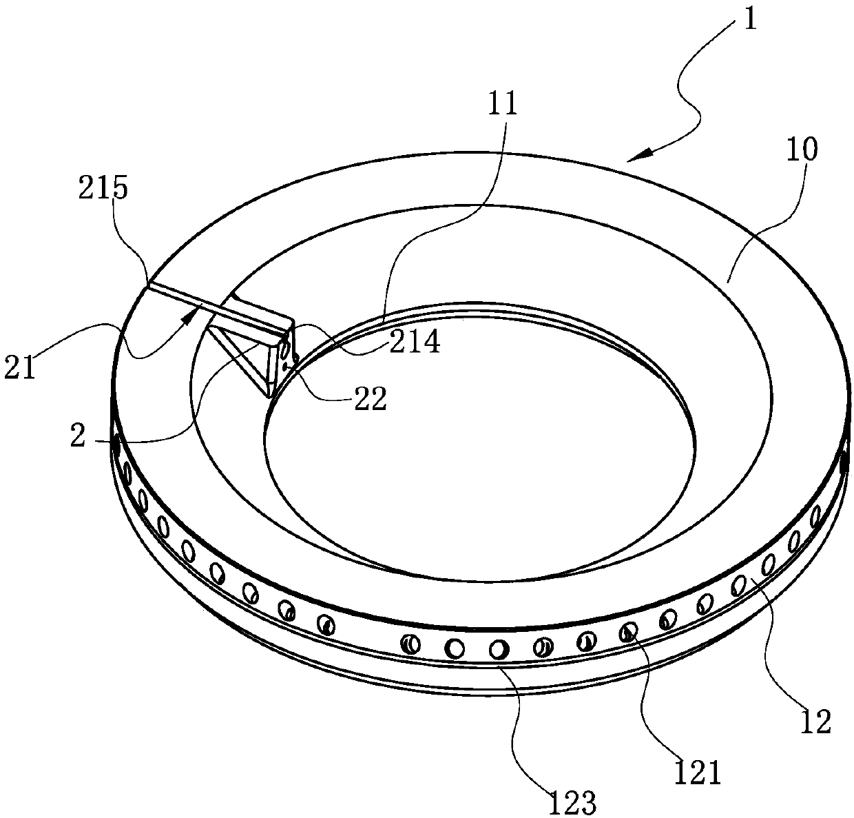
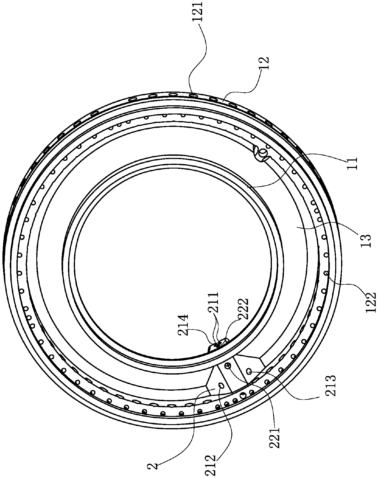
[0025] like Figure 1~5 Shown is the preferred embodiment of the present invention. The fire cover used for the gas stove in this embodiment includes a fire cover body 1, and the annular top wall 10 of the fire cover body 1 extends vertically or obliquely downward from the inner edge and the outer edge of the annular top wall 10. The inner ring wall 11 and the outer ring wall 12 of the inner ring wall 11 and the outer ring wall 12 form a mixing chamber 13, and on the upper surface of the fire cover body 1, there is a transmission tube extending radially outward toward the center of the fire cover body 1 from the inner ring wall 11 to the outer ring wall 12. The fire chamber 2, the top wall of the fire transmission chamber 2 is provided with a fire induction groove 21, and among the two opposite inner side walls of the top opening of the fire induction groove 21, at least one side wall has a protruding towards the other side wall and extends radially. The raised rib 211 and th...

Embodiment 2

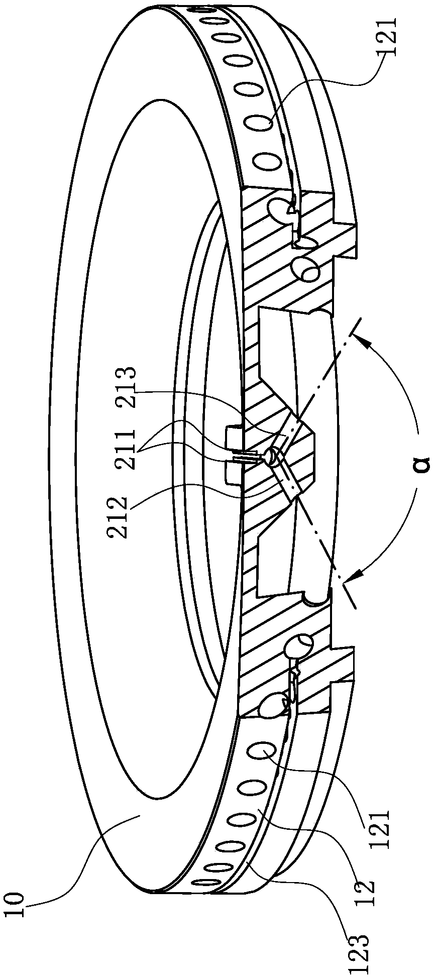
[0029] The structure is basically the same as that of Embodiment 1, the only difference is in one place: there is no boss 3, the first through hole 212 and the second through hole 213, the clip where the centerlines of the first through hole 212 and the second through hole 213 intersect The angle α is an obtuse angle, and the impact force of the two relative collisions is greater, so that the gas flowing out of the first through hole 212 and the second through hole 213 is relatively opposed, thereby improving the mixing uniformity of the gas and air in the ignition groove 21, At the same time, the flow rate is reduced and the flame stability performance is improved, such as Image 6 shown.


PUM


Abstract

The invention relates to a burner cap used for a gas stove. The burner cap comprises a burner cap body. The burner cap body comprises a gas mixing cavity. A fire transfer chamber is arranged on the upper surface of the burner cap body. A fire leading groove is formed in the top wall of the fire transfer chamber. The burner cap is characterized in that in the two opposite inner side walls of a topopening of the fire leading groove, protruding ribs protruding towards the other side wall and extending in the radial direction are arranged on at least one side wall; and at least one through hole which communicates with the gas mixing cavity and comprises an opening facing the protruding ribs is formed in the other part, except the top opening, of the fire leading groove. Compared with the prior art, the burner cap has the advantages that the at least one through hole communicating with the gas mixing cavity is formed in the other part, except the top opening communicating with the outsideworld, in the fire leading groove, the center line of each through hole intersects with the corresponding protruding edge, and therefore fuel gas flowing out from each through hole can oppositely flush the corresponding protruding edge, and therefore the mixing uniformity of the fuel gas in the fire leading groove and air is improved.

Description

technical field [0001] The invention relates to a burner for a gas stove, in particular to a fire cover for a gas stove. Background technique [0002] At present, most of the traditional burner fire caps sold on the market are milled with one groove, that is, a fire pilot groove is milled on the top of the fire cap body. If disconnected, it is easy to cause deformation of the fire cover body, thereby affecting the ignition effect. For example, the Chinese invention patent "Gas burner with fire transmission device and flameout protection function" whose patent number is 201220464214.0 (notification number is CN202813375U) discloses a similar fire transmission structure. ring fire hole, and the outer ring fire transmission device is also provided on the outer ring fire spray right, the outer ring fire transmission device is a boss installed on the inner wall of the outer ring fire spray ring The outer ring fire transmission hole and the outer ring fire transmission groove on...

Claims


Application Information

Patent Timeline
Patent Type & Authority Applications(China)
IPC IPC(8): F23D14/04F23D14/26F23D14/46F23D14/58F23D14/64F23L9/00
CPCF23D14/04F23D14/26F23D14/46F23D14/58F23D14/64F23L9/00
Inventor 方晓艳李林严力峰钟健郑军妹俞瑜
Owner NINGBO FOTILE KITCHEN WARE CO LTD
Why Eureka
Try Eureka