Automatic drying machine controlled by PLC

A technology of drying machine and drying rack, which is applied in the direction of static material drying machine, partial mixing drying machine, drying machine, etc., which can solve the inconvenience of installation and disassembly of drying plate and body, affect the cleaning and replacement of drying plate, and inconvenient movement of drying plate, etc. problem, to achieve the effect of simple structure, convenient centralized pick and place, easy cleaning and replacement

Inactive Publication Date: 2020-06-09
ZHENGZHOU TECHN COLLEGE
View PDF6 Cites 0 Cited by
  • Summary
  • Abstract
  • Description
  • Claims
  • Application Information

AI Technical Summary

Problems solved by technology

[0003] The existing dryer still has the following problems in the process of use: when opening the dryer through the door and taking and placing the materials inside the dryer, the door is inconvenient to fix, and it is easy to swing by itself under force, which affects the picking and placing of materials; The material to be dried is laid flat on the drying plate, and then the material on the drying plate is dried by the dryer. The installation and disassembly between the drying plate and the body is inconvenient, which affects the cleaning and replacement of the drying plate; the drying machine and the drying plate inside the dryer The overall movement is relatively inconvenient. When picking and placing materials, the materials or receiving device can only be transported to the vicinity of the dryer for picking and placing, which is inconvenient to use

Method used


Image

  • Automatic drying machine controlled by PLC
  • Automatic drying machine controlled by PLC
  • Automatic drying machine controlled by PLC

Examples


Embodiment

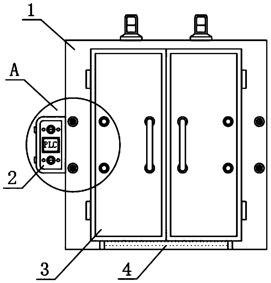
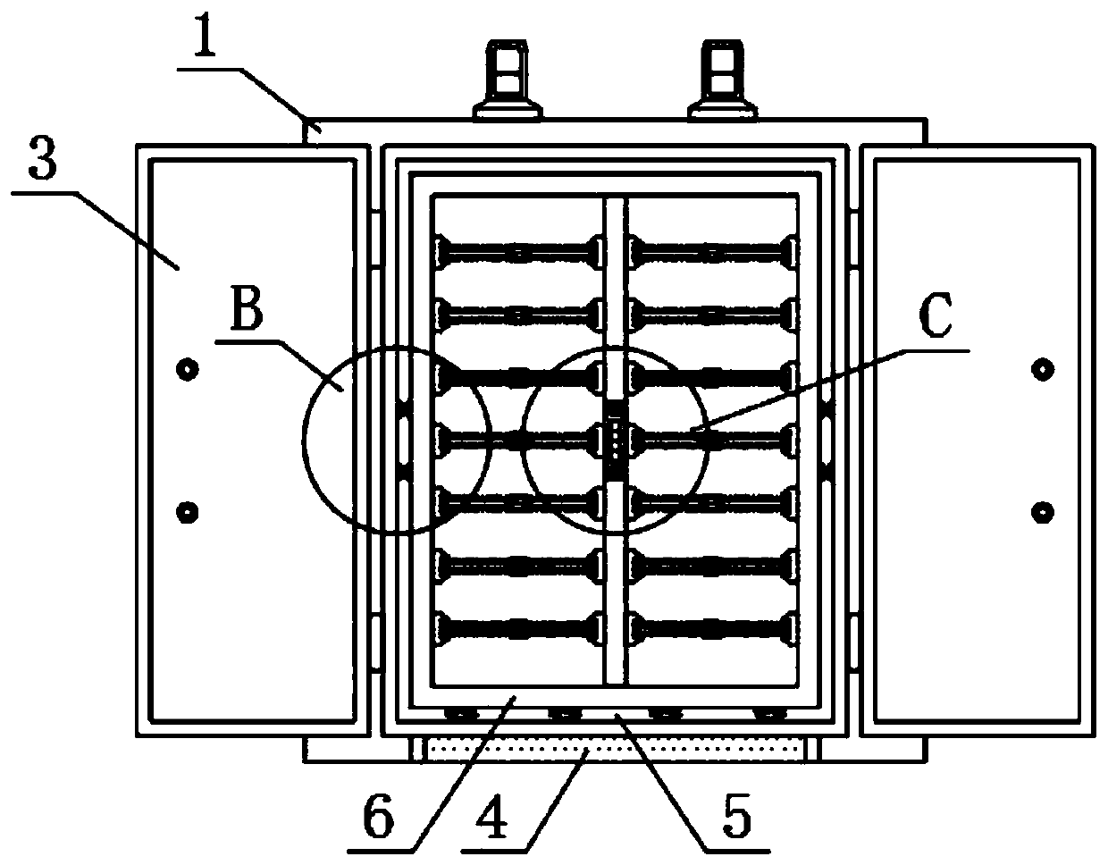
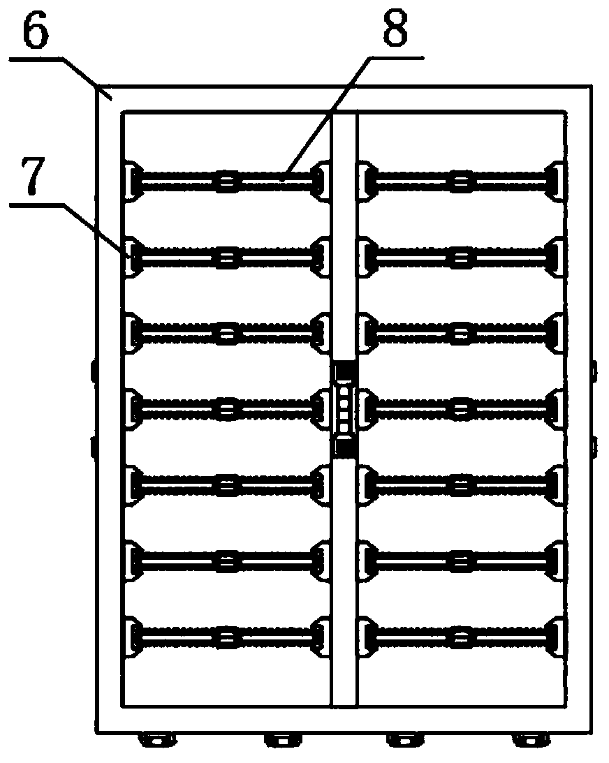
[0025] see Figure 1-8 , the present invention provides the following technical solutions: a PLC-controlled automatic dryer, including a dryer body 1, one side of the dryer body 1, the left and right ends are connected to the door 3 through the rotation of the shaft, the outer surface of the dryer body 1 Several magnetic suction cylinders 10 are fixed on the left and right ends of one side, and several magnetic suction heads 11 are fixed on one side of the outer surface of the warehouse door 3. The inside of the dryer body 1 is provided with a drying chamber 5, and the interior of the drying chamber 5 is provided with Drying frame 6 is arranged, and the both sides of inner surface of drying chamber 5 are all screwed and connected with several rotating shafts 12, and the both sides of outer surface of drying frame 6 are all fixed with several rotary cylinders 13, and the both sides of inner surface of drying frame 6 are arranged on both sides. It is fixed on a number of card ho...


PUM


Abstract

The invention belongs to the technical field of drying, and particularly relates to an automatic drying machine controlled by a PLC. The drying machine comprises a drying machine body, wherein bin doors are rotationally connected to the left end and the right end of one side of the drying machine body through rotating shafts, a plurality of magnetic attraction cylinders are fixed to each of the left end and the right end of one side of the outer surface of the drying machine body, a plurality of magnetic attraction heads are fixed to one sides of the outer surfaces of the bin doors, a drying cavity is formed in the drying machine body, a drying frame is arranged in the drying cavity, a plurality of screwing shafts are connected to each of the two sides of the inner surface of the drying cavity in a screwed mode, a plurality of screwing cylinders are fixed to each of the two sides of the outer surface of the drying frame, a plurality of clamping bases are fixed to each of the two sidesof the inner surface of the drying frame, drying plates are connected into the clamping bases in a clamped mode, a plurality of air holes are formed in the surfaces of the drying frame and the dryingplates, and during use, the drying frame drives the drying plates to be pushed in and out of the drying machine body, so that materials are conveniently taken and placed in a centralized mode, and meanwhile, the screwing shafts and the screwing cylinders are screwed together correspondingly, so that the drying frame is conveniently and stably fixed.

Description

technical field [0001] The invention belongs to the technical field of drying, and in particular relates to a PLC-controlled automatic drying machine. Background technique [0002] Dryer refers to a kind of mechanical equipment that uses heat energy to reduce the moisture of materials. The dryer vaporizes and escapes the moisture in materials by heating to obtain solid materials with specified water content. The purpose of drying is to meet the further processing needs of materials. According to the operating pressure, dryers are divided into two types: normal pressure dryers and vacuum dryers. With the wide application of dryers in food, chemical, pharmaceutical, light and heavy industries and other related industries, dryers are moving towards automation and intelligence. The direction is constantly innovating and developing. For example, a domestic company currently produces and sells a model CT-C, an automatic dryer based on PLC control, which has been widely used in var...

Claims


Application Information

Patent Timeline
Patent Type & Authority Applications(China)
IPC IPC(8): F26B9/06F26B25/00F26B25/10F26B25/12F26B25/18
CPCF26B9/06F26B25/00F26B25/001F26B25/10F26B25/12F26B25/18
Inventor 李道军卢青波李性珂闫生辉王辉
Owner ZHENGZHOU TECHN COLLEGE
Why Eureka
Try Eureka