Display device
A technology for display devices and handheld devices, applied to identification devices, instruments, etc., can solve the problems of difficult grip, difficult operation, and poor portability for users, and achieve the effects of improving comfort, anti-skid performance, and handheld stability
- Summary
- Abstract
- Description
- Claims
- Application Information
AI Technical Summary
Problems solved by technology
Method used
Image
Examples
Embodiment 1
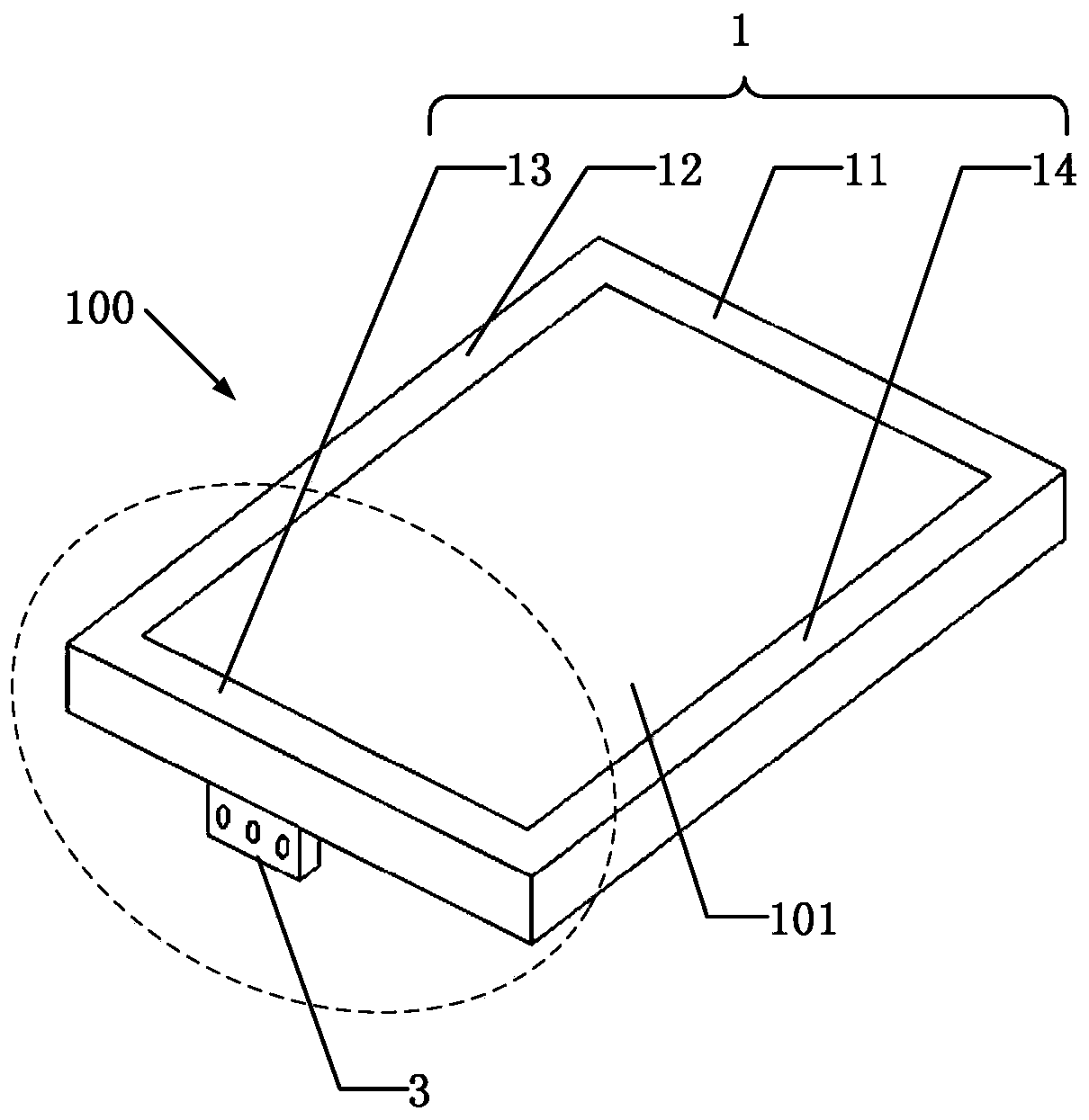
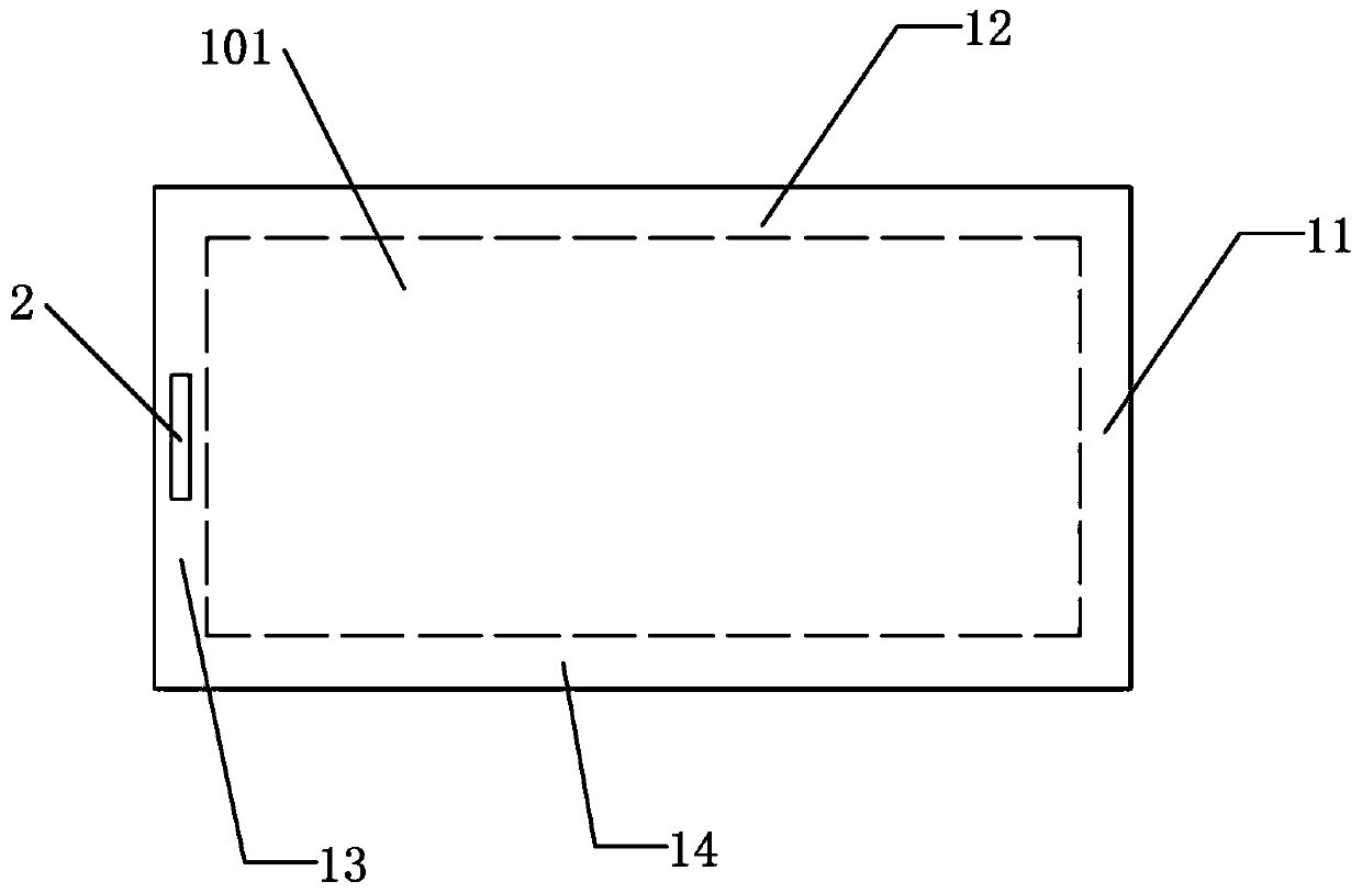
[0045] Such as figure 1 , figure 2 As shown, this embodiment provides a display device 100 , which includes: a housing 1 , a sliding slot 2 and a handheld device 3 .
[0046] Such as figure 1 As shown, the display device 100 includes a display area 101 , and the casing 1 is disposed around the display area 101 . The housing 1 is surrounded by a first frame 11, a second frame 12, a third frame 13 and a fourth frame 14 connected end to end, the first frame 11 is opposite to the third frame 13, and the first frame 11 The second frame 12 is opposite to the fourth frame 14 .
[0047] Such as figure 1 , figure 2 As shown, the chute 2 is recessed on the outer surface of the frame. In this embodiment, the chute 2 is recessed in the bottom surface of the third frame 13 .
[0048] Such as figure 1 , figure 2 As shown, the handheld device 3 can be slidably inserted into the sliding slot 2 .
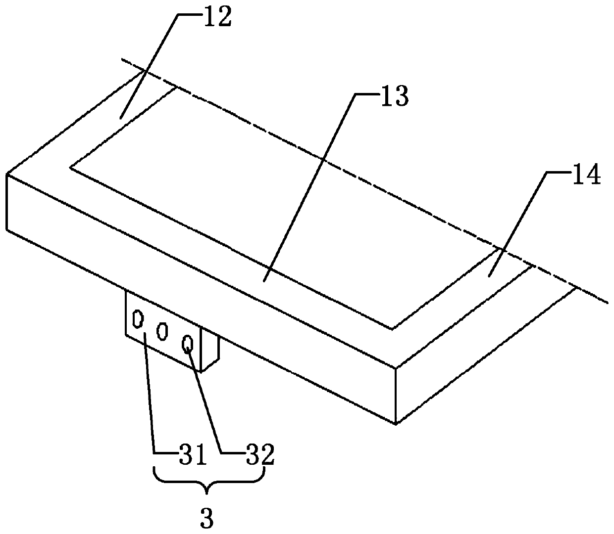
[0049] Such as image 3 As shown, the handheld device 3 includes a telescopic plat...
Embodiment 2
[0054] Such as Figure 6 , Figure 7 As shown, this embodiment includes most of the technical features of Embodiment 1. The difference from Embodiment 1 is that the chute 2 in this embodiment is recessed on the side of the third frame 13 instead of Embodiment 1. The chute 2 in the middle is recessed in the bottom surface of the third frame 13 .
[0055] Such as Figure 6As shown, the telescopic plate 31 in this embodiment is a bendable structure. The bendable structure includes a first board 311 and a second board 312 . The second board 312 is hinged to the first board 311 through a hinge mechanism 313 . That is, the second plate body 312 can be turned over 90 degrees relative to the first plate body 311 through the hinge mechanism 313, so that fingers can extend into the through hole 32 on a plane parallel to the display area 101, improving the customer experience and comfort .
[0056] By arranging the handheld device 3 on the outer frame of the housing 1 of the displa...
Embodiment 3
[0058] Such as Figure 8 As shown, this embodiment includes most of the technical features of Embodiment 1, and the difference from Embodiment 1 is that the display device 100 described in this embodiment is a foldable display device.
[0059] Such as Figure 8 As shown, the display device 100 of this embodiment includes a first panel 5 and a second panel 6 . The second panel 6 is hinged on the first panel 5 . When the display device 100 is unfolded, the first panel 5 and the second panel 6 form a display area 101 , and the casing 1 is arranged around the display area 101 .
[0060] Such as Figure 8 As shown, the display device 100 also includes a limiting groove 7 and a limiting block 8 . When the display device 100 is folded, when the first panel 5 and the second panel 6 are folded to overlap each other, the limiting block 8 is embedded in the limiting groove 7, so as to avoid misalignment when the display device 100 is folded.
[0061] By arranging the handheld device...
PUM
 Abstract
Description
Claims
Application Information
 - R&D
- Intellectual Property
- Life Sciences
- Materials
- Tech Scout
- Unparalleled Data Quality
- Higher Quality Content
- 60% Fewer Hallucinations
Browse by: Latest US Patents, China's latest patents, Technical Efficacy Thesaurus, Application Domain, Technology Topic, Popular Technical Reports.
© 2025 PatSnap. All rights reserved.Legal|Privacy policy|Modern Slavery Act Transparency Statement|Sitemap|About US| Contact US: help@patsnap.com


