Flying fork winding mechanism with eccentric shaft positioning middle guard

A winding mechanism and eccentric shaft technology, applied in the direction of electromechanical devices, manufacturing motor generators, electrical components, etc., can solve the problems of inability to realize continuous and gapless winding, affecting the full rate of stator slots, and winding chaos, etc. Achieve continuous gapless winding, improve slot fullness, and stable winding

Active Publication Date: 2022-03-11
周长松
View PDF4 Cites 0 Cited by
  • Summary
  • Abstract
  • Description
  • Claims
  • Application Information

AI Technical Summary

Problems solved by technology

The above two methods are extremely unstable during the winding process, and winding chaos is prone to occur. Not only cannot continuous and gap-free winding be achieved, but also affect the slot fullness of the stator.

Method used


Image

  • Flying fork winding mechanism with eccentric shaft positioning middle guard
  • Flying fork winding mechanism with eccentric shaft positioning middle guard
  • Flying fork winding mechanism with eccentric shaft positioning middle guard

Examples


Embodiment Construction

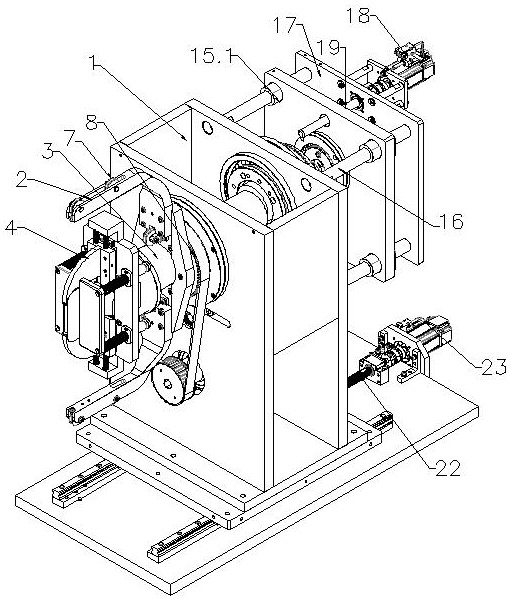
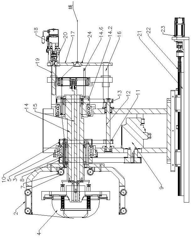
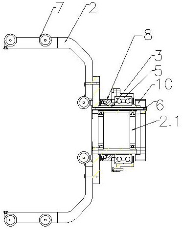
[0026] Now in conjunction with the accompanying drawings, the present invention is described in further detail. The following are only preferred embodiments of the present invention, and are not intended to limit the protection scope of the present invention. Any equivalent or similar replacements without departing from the concept of the present invention shall fall within the protection scope of the present application. And the following parts that are not exhaustive should be carried out according to the existing technology or conventional technology in this field, such as "fixing", "fixing in a conventional way", "connecting", etc., can all adopt conventional fixed connection methods such as bolts and screws, and The following descriptions of "bearing housings" refer to bearing housings that already contain bearings.

[0027] Such as Figure 1-8As shown, the flying fork winding mechanism with an eccentric shaft positioning the middle claw of the present invention include...


PUM


Abstract

The invention discloses a flying fork winding mechanism with an eccentric shaft positioning the middle claw, comprising a base, a flying fork mechanism, and a claw protecting module, wherein the flying fork mechanism includes a flying fork rod, a flying fork main shaft and driving the flying fork main shaft to rotate The first driving mechanism of the action, the main shaft of the flying fork is a hollow shaft; the eccentric shaft module and the eccentric rod module that do not rotate with the main shaft of the flying fork are also fixed on the base, and the eccentric shaft in the eccentric shaft module passes through the hollow shaft. The claw guard module is positioned after the flying fork main shaft, and the eccentric rod in the eccentric rod module passes through the hollow eccentric shaft and pushes the claw guard module to move under the drive of the second drive mechanism. The structure design of the present invention is very reasonable, and compared with the existing structure, it is more precise, and the wound out motor stator coils are continuous and uniform without gaps, and are especially suitable for winding around outer rotor motor stators and straight stator coils.

Description

technical field [0001] The invention relates to a motor stator winding mechanism, in particular to a flying fork winding mechanism with an eccentric shaft positioning the middle claw, and belongs to the technical field of motor production. Background technique [0002] The stator of the motor is the static part of the motor. The stator is composed of three parts: the stator core, the stator winding and the machine base. The stator winding is usually wound on the stator core by a flying fork winding mechanism. The flying fork winding mechanism in the prior art generally includes a power source, an eccentric wheel, a guide rod, a slider and a flying fork rod. The rod moves up and down, and then the flyer rod fixed with the slider will also move up and down, realizing the pulling effect of the flyer rod on the copper wire. The above-mentioned flying fork winding mechanism is suitable for the stator winding made by the process of first winding the winding as a whole and then in...

Claims


Application Information

Patent Timeline
Patent Type & Authority Patents(China)
IPC IPC(8): H02K15/085
CPCH02K15/085
Inventor 周长松
Owner 周长松
Why Eureka
Try Eureka