Chassis structure of swivel chair

A swivel chair and chassis technology, applied to chairs, chairs with vertically adjustable seats, stools, etc., can solve the problems of difficult and thin design, general transmission stability, and many parts, and achieve simple, ingenious and reasonable structure, and gear transmission The effect of smooth flow and reduced number of parts

Pending Publication Date: 2020-06-12
中山市继文家具有限公司
View PDF0 Cites 2 Cited by
  • Summary
  • Abstract
  • Description
  • Claims
  • Application Information

AI Technical Summary

Problems solved by technology

[0002] In order to provide the comfort of the seat, people have invented swivel chairs that can be lifted, tilted and rotated. The swivel chair is mainly composed of chair feet, air pressure rods, cylinders, chassis structures, cushions, and backrests. structure, the design of the free angle locking structure of the existing chassis structure is cumbersome and complicated, and the structural design is unreasonable. Generally, it is a translational transmission structure composed of a transmission rod, a transmission plate, and a spring, and the transmission of the translational transmission structure is not enough. Stable and smooth, slow transmission speed, low adjustment efficiency of turning the Xiaoyao lock handle, average transmission stability, large design space required, large bottom shell thickness, difficult to carry out thin and light design, and many parts and many production processes, resulting in production High cost and uncompetitive products

Method used


Image

  • Chassis structure of swivel chair
  • Chassis structure of swivel chair
  • Chassis structure of swivel chair

Examples


Embodiment Construction

[0018] It should be understood that the specific embodiments described here are only used to explain the present invention, not to limit the present invention.

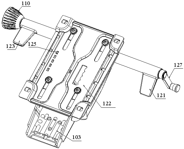
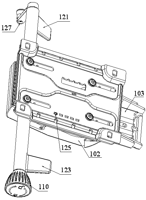
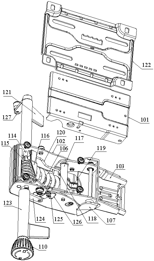
[0019] refer to Figure 1 to Figure 5 , an embodiment of the chassis structure of the swivel chair of the present invention is proposed, including a bottom plate 101, a bottom shell 102 installed on the lower side of the bottom plate 101, a tail plate 103 linked with the backrest, a tilting and free structure that can realize the tilting function, The escape angle locking structure with adjustable escape angle.

[0020] The tilting free structure includes a fulcrum 104 that is connected between the tail plate 103 and the bottom shell 102 and acts as a fulcrum, a rotating shaft 105 that is connected between the tail plate 103 and the bottom shell 102 and can rotate around the fulcrum 104, and is located on The compression spring 106 inside the bottom shell 102 and plays a role in returning the rotating shaft 105 . Th...


PUM


Abstract

The invention discloses a chassis structure of a swivel chair. The chassis structure comprises a bottom plate, a bottom shell mounted on the lower side of the bottom plate, a tail plate linked with abackrest, a tipping leisure structure capable of realizing a tipping leisure function, and a leisure angle locking structure capable of adjusting a leisure angle, the tipping leisure structure comprises a fulcrum shaft which is connected between the tail plate and the bottom shell and plays a fulcrum role, a rotating shaft which is connected between the tail plate and the bottom shell and can rotate around the fulcrum shaft, and a pressure spring which is arranged in the bottom shell and plays a return role on the rotating shaft; the leisure angle locking structure comprises a leisure lockinghandle arranged on the outer side of the bottom shell, gear locking teeth located in the base and provided with a plurality of gear holes, locking pins arranged in the leisure locking handle and capable of being inserted into the corresponding gear holes in a clamped mode, and gear pieces arranged on the supporting shaft and the rotating shaft in a sleeving mode. A first arc-shaped tooth edge is arranged on the gear locking teeth, a second arc-shaped tooth edge in meshed transmission with the first arc-shaped tooth edge is arranged on the gear piece, and the gear locking teeth and the gear piece are in meshed transmission to form a split type gear transmission structure.

Description

technical field [0001] The invention relates to the technical field of the swivel chair, in particular to the chassis structure of the swivel chair. Background technique [0002] In order to provide the comfort of the seat, people have invented swivel chairs that can be lifted, tilted and rotated. The swivel chair is mainly composed of chair feet, air pressure rods, cylinders, chassis structures, cushions, and backrests. structure, the design of the free angle locking structure of the existing chassis structure is cumbersome and complicated, and the structural design is unreasonable. Generally, it is a translational transmission structure composed of a transmission rod, a transmission plate, and a spring, and the transmission of the translational transmission structure is not enough. Stable and smooth, slow transmission speed, low adjustment efficiency of turning the Xiaoyao lock handle, average transmission stability, large design space required, large bottom shell thicknes...

Claims


Application Information

Patent Timeline
Patent Type & Authority Applications(China)
IPC IPC(8): A47C3/18A47C3/30A47C7/00
CPCA47C3/18A47C3/30A47C7/002
Inventor 翁永联
Owner 中山市继文家具有限公司
Why Eureka
Try Eureka