Working frame for machining

A machining and work frame technology, applied in the direction of grinding workpiece supports, metal processing equipment, metal processing machinery parts, etc., can solve problems such as poor applicability, weak adjustment ability, and inability to process parts, and achieve convenient installation and removal. Practicality and functionality, the effect of good stability

Inactive Publication Date: 2020-06-12
WEST ANHUI UNIV
View PDF0 Cites 2 Cited by
  • Summary
  • Abstract
  • Description
  • Claims
  • Application Information

AI Technical Summary

Problems solved by technology

[0003] At present, most of the commonly used mechanical processing equipment are cutting machines, grinding machines, etc. These equipments themselves have fixing devices and clamping devices, but when the fixing devices and clamping devices are damaged, the parts cannot be processed normally, which in turn affects production ; In addition, the fixing device and clamping device carried by the device itself will have weak adjustment ability due to the space of the device during use, making the overall applicability poor.

Method used


Image

  • Working frame for machining
  • Working frame for machining
  • Working frame for machining

Examples


Embodiment 1

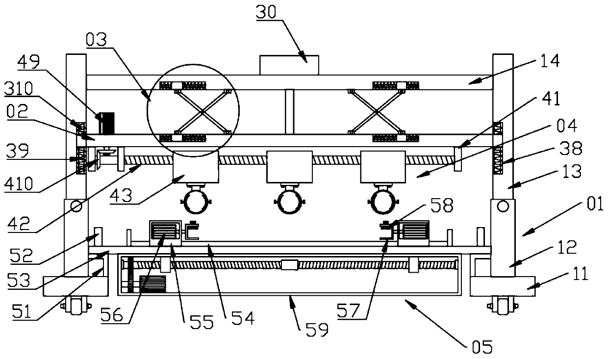
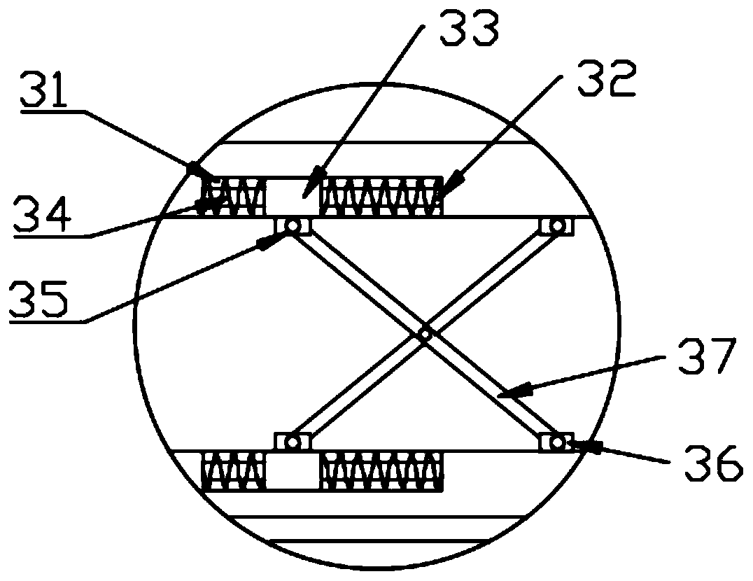
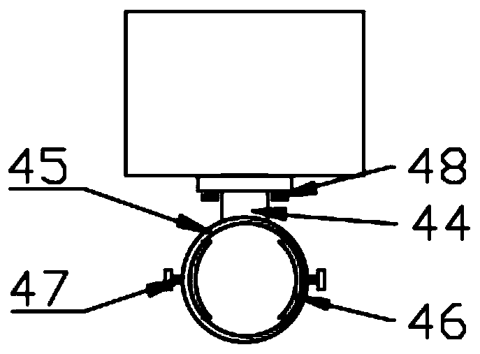
[0026] see Figure 1~3 , in an embodiment of the present invention, a working frame for mechanical processing includes a bracket assembly 01, the bracket assembly 01 is used to play a role in supporting the whole, and can improve the overall stability; the bracket assembly 01 is slidably connected with a support Plate 02, that is, the support plate 02 can slide on the support assembly 01, and then the position of the support plate 02 can be adjusted; the support assembly 01 and the support plate 02 are provided with a height adjustment assembly 03, through which the height adjustment assembly 03 can play a role The adjustment function of the support plate 02 can also improve its stability while adjusting, and has very good practicability; in addition, the support plate 02 is also equipped with a level adjustment component 04, and the level adjustment component 04 is equipped with a clamping Assemblies, the horizontal adjustment assembly 04 can drive the clamping assembly to mo...

Embodiment 2

[0034] The bracket component 01 is also provided with an auxiliary fixing component 05, which can play an auxiliary fixing role through the auxiliary fixing component 05, thereby making it more convenient to fix the parts, and at the same time it is convenient to disassemble. When it is not needed, it can be directly removed , making the overall applicability better.

[0035] Further, the auxiliary fixing assembly 05 includes a backing plate 51 fixed on the bracket assembly 01, an insertion rod 52 is fixed above the backing plate 51, and a placement plate 53 is inserted on the insertion rod 52. When installing, directly place the placement plate 53 is inserted on two inserting rods 52 and can finish the installation of placing plate 53, very simple; Said placing plate 53 is fixed with slide rail 54, and slide rail 54 is slidably connected with mobile box 55, and promptly mobile box 55 can Slide on slide rail 54, and then adjust the position of mobile box 55, be provided with s...


PUM


Abstract

The invention discloses a working frame for machining, and relates to the field of machining. The working frame for machining comprises a support assembly, wherein a supporting plate is connected to the support assembly in a sliding mode; height adjusting assemblies are arranged on the support assembly and the supporting plate; a horizontal adjusting assembly is further arranged on the supportingplate; a clamping assembly is arranged on the horizontal adjusting assembly; and an auxiliary fixing assembly is further arranged on the support assembly, so that the whole working frame has very goodadjusting capacity, meanwhile, the working frame is suitable for machining of various parts and is used for various machining equipment, and very good applicability is achieved.

Description

technical field [0001] The invention relates to the field of machining, in particular to a working frame for machining. Background technique [0002] Machining refers to the process of changing the shape or performance of a workpiece through a mechanical device. According to the difference in processing methods, it can be divided into cutting processing and pressure processing. During the machining process, cutting and processing are often required on the workbench. Polishing and other processes. [0003] At present, most of the commonly used mechanical processing equipment are cutting machines, grinding machines, etc. These equipments themselves have fixing devices and clamping devices, but when the fixing devices and clamping devices are damaged, the parts cannot be processed normally, which in turn affects production In addition, the fixing device and clamping device carried by the device itself will have weak adjustment ability due to problems such as the space of the d...

Claims


Application Information

Patent Timeline
Patent Type & Authority Applications(China)
IPC IPC(8): B23Q3/06B23Q1/25B24B41/06
CPCB23Q1/25B23Q3/06B24B41/06
Inventor 吴从兵周红霞黄林李鸿宾
Owner WEST ANHUI UNIV
Why Eureka
Try Eureka