An automatic marking equipment for wood-plastic panels
A technology for printing labels and plates, applied in printing, printing devices, typewriters, etc., can solve the problems of low work efficiency, labor consumption, and long time, and achieve the effect of saving labor and improving efficiency
- Summary
- Abstract
- Description
- Claims
- Application Information
AI Technical Summary
Problems solved by technology
Method used
Image
Examples
Embodiment 1
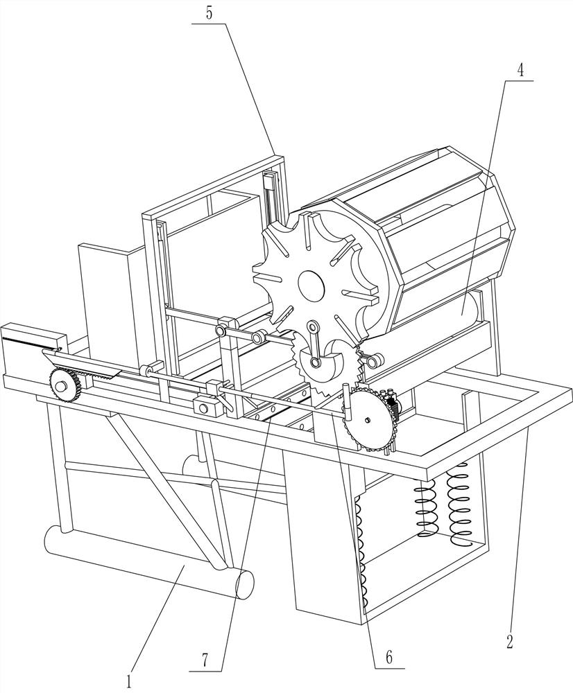
[0023] An automatic marking equipment for wood-plastic panels, such as Figure 1-3 As shown, it includes a frame 1, a loop frame 2 and a mounting plate 3. The loop frame 2 is connected to the top of the frame 1, and the loop frame 2 is connected to the frame 1 by bolts. The top of the loop frame 2 Both sides are connected with the mounting plate 3, and also include a geared motor 301, a first gear 302, a feeding mechanism 4 and a marking device 5, and the top of the return frame 2 is also connected with a geared motor 301, and the geared motor 301 is located on the mounting plate 3 On the front side, the reduction motor 301 is connected with the first gear 302, the feeding mechanism 4 is arranged between the mounting plates 3 on both sides, the marking device 5 is arranged between the return frame 2 and the feeding mechanism 4, and the marking device 5 It is used to print labels on plastic wood boards, and the feeding mechanism 4 is connected to the label printing device 5 thr...
Embodiment 2
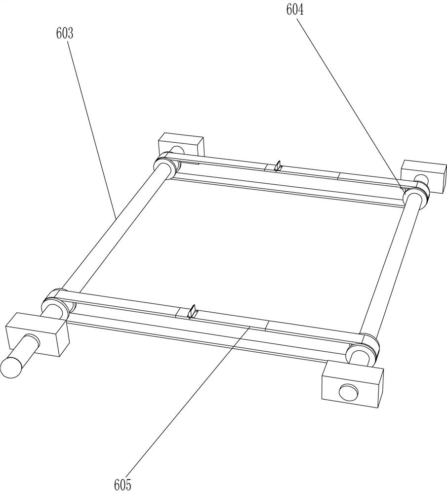
[0028]On the basis of Example 1, such as Figure 3-7 As shown, it also includes a feeding assembly 6, and the feeding assembly 6 includes a push rod 601, a trapezoidal rack 602, a rotating shaft 603, a flat pulley 604, a flat belt 605, a third gear 606, a connecting block 607, and a return spring 608 , push block 609, stop block 610, torsion spring 611 and limit frame 612, and the left side support column 502 outside lower part is slidingly connected with push rod 601, and one end of push rod 601 is positioned on the rotation track of intermittent transmission rod 406 and intermittent transmission rod 406, the other end of the push rod 601 is connected with a trapezoidal rack 602, and two rotating shafts 603 are rotationally connected between the two sides of the rear part of the return frame 2. Both are connected with a flat pulley 604, a flat belt 605 is wound between the flat pulleys 604 of the two rotating shafts 603, a through groove is opened on both sides of the top of ...
Embodiment 3
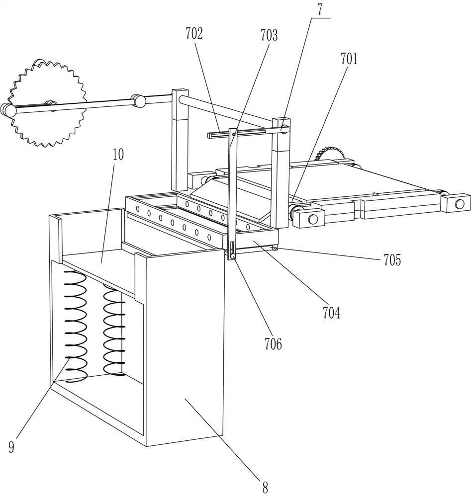
[0031] On the basis of Example 2, such as Figure 8 As shown, a drying assembly 7 is also included, and the drying assembly 7 includes a guide plate 701, a connecting rod 702, a slide bar 703, a drying box 704, a bottom plate 705 and a clamping rod 706, and the right end of the transmission shaft of the transmission frame 507 passes through The support column 502 on the right side is connected with connecting rod 702, is connected with guide plate 701 on the printing base 508, and guide plate 701 plays a guiding role, is connected with drying box 704 between both sides in the back shape frame 2, and drying box 704 is used. To dry the plastic-wood board, the discharge part of the guide plate 701 is aligned with the drying box 704, and a slide bar 703 is slidably connected to one side of the return frame 2, and the slide bar 703 is slidably matched with the connecting rod 702, and the bottom of the drying box 704 is A bottom plate 705 is hingedly connected, and one side of the b...
PUM
 Abstract
Description
Claims
Application Information
 - R&D
- Intellectual Property
- Life Sciences
- Materials
- Tech Scout
- Unparalleled Data Quality
- Higher Quality Content
- 60% Fewer Hallucinations
Browse by: Latest US Patents, China's latest patents, Technical Efficacy Thesaurus, Application Domain, Technology Topic, Popular Technical Reports.
© 2025 PatSnap. All rights reserved.Legal|Privacy policy|Modern Slavery Act Transparency Statement|Sitemap|About US| Contact US: help@patsnap.com


