Hinge type bent positioning support

A positioning support and hinged technology, applied in the direction of overhead lines, etc., can solve the problems of positioner horizontal rotation adjustment and vertical lift limit, damage to parts and pipes, and weak bearing capacity of shackles, etc., to achieve maintenance and operation Convenience, prolong service life, realize the effect of horizontal deflection and vertical lift adjustment

Pending Publication Date: 2020-06-12
宝鸡保德利电气设备有限责任公司
View PDF2 Cites 1 Cited by
  • Summary
  • Abstract
  • Description
  • Claims
  • Application Information

AI Technical Summary

Problems solved by technology

The prior art closest to the present invention is "Bending Aluminum Alloy Positioning Support CN200920034075.6", although this support can meet the requirements of the large lifting amount and large pull-out value of the pantograph in terms of height and horizontal space. The use requirements, but because the support adopts the "V" surface + U bolt connection form, forming point contact and stress concentration, it is easy to cause great damage to the part itself and the pipe, and the structural force is unreasonable.
Moreover, the connection between the support and the locator follows the traditional hook-and-loop connection structure, which not only has problems such as abnormal wear, gap discharge corrosion, and weak bearing capacity of the shackle, but also limits the horizontal rotation adjustment and vertical lift of the locator.

Method used


Image

  • Hinge type bent positioning support
  • Hinge type bent positioning support
  • Hinge type bent positioning support

Examples


Embodiment Construction

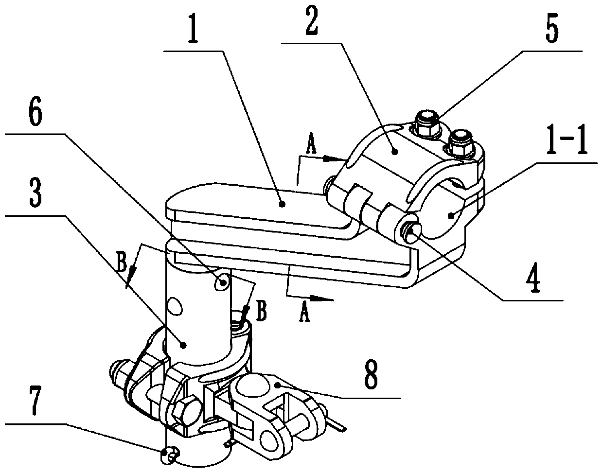
[0018] Attached below Figure 1-5 The present invention will be described in detail with specific embodiments.

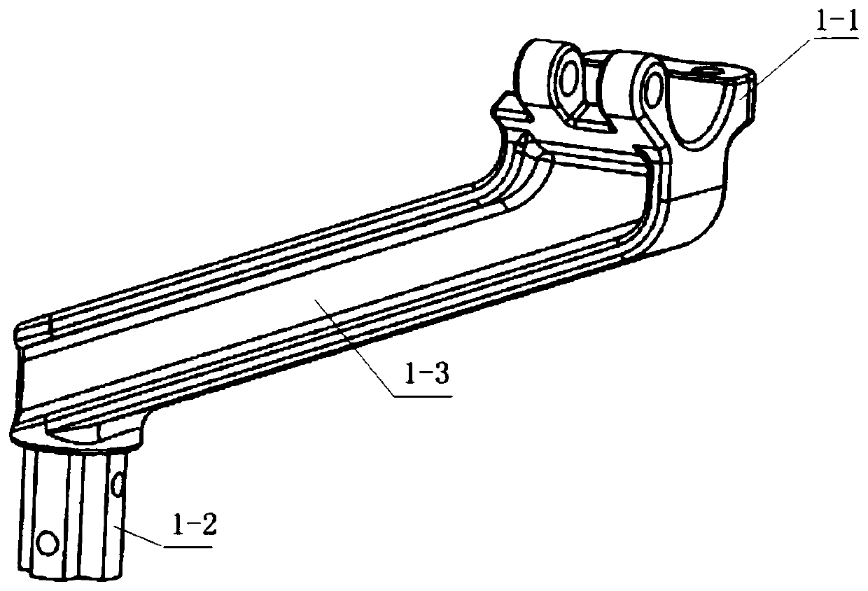
[0019] A hinged bending type positioning support, which is composed of a bending type connecting seat 1, an upper hoop 2, a limit tube 3 and a positioner support 8; the bending type connecting seat 1 has a lower hoop 1- 1. It is composed of a support arm 1-3 connected under the lower hoop 1-1 and inclined downward, and a positioning column 1-2 connected to the lower end of the support arm 1-3; one side of the upper hoop 2 is passed through a pin 4 Hinged on one side of the lower hoop 1-1, the other side of the upper hoop 2 is connected with the other side of the lower hoop 1-1 through the bolt pair 5; the positioning column 1-2 is inserted in the The upper end of the limit tube 3 is riveted radially by the rivet 6 to fix the limit tube 3 on the positioning column 1-2; the locator support 8 is sleeved on the limit tube 3 .

[0020] The locator support 8 is the appl...


PUM


Abstract

The invention discloses a hinge type bent positioning support. The support consists of a bent connecting seat, an upper hoop, a limiting pipe and a positioner support; and the bent connecting seat iscomposed of a lower hoop, a supporting arm which is connected to the lower portion of the lower hoop and inclines downwards, and a positioning column connected to the lower end of the supporting arm.One side of the upper hoop is hinged to one side of the lower hoop through a pin, and the other side of the upper hoop is connected with the other side of the lower hoop through a bolt pair. The positioning column is inserted into the upper end of the limiting pipe, and the limiting pipe is fixed to the positioning column through rivets in the radial direction in a riveted mode. The positioner support is sleeved on the limiting pipe. The defects in the prior art are overcome.

Description

technical field [0001] The invention belongs to the technical field of electrified railway catenary component manufacturing, and in particular relates to a hinged bending type positioning support. Background technique [0002] The tension of contact wire and catenary cable of high-speed electrified railway is much higher than that of general line, and the corresponding lifting amount of pantograph and pull-out value of contact wire are higher than that of general line. The prior art closest to the present invention is "Bending Aluminum Alloy Positioning Support CN200920034075.6", although this support can meet the requirements of the large lifting amount and large pull-out value of the pantograph in terms of height and horizontal space. However, because the support adopts the "V" surface + U bolt connection form, forming point contact and stress concentration, it is easy to cause great damage to the part itself and the pipe, and the structural force is unreasonable. Moreove...

Claims


Application Information

Patent Timeline
Patent Type & Authority Applications(China)
IPC IPC(8): B60M1/20
CPCB60M1/20
Inventor 路海健闫军芳黄婷赵思雨宋卫卫张晓辉张召严小娜李海峰
Owner 宝鸡保德利电气设备有限责任公司
Why Eureka
Try Eureka