A connection structure of a cross bar

A technology of connecting structure and cross-bar, applied in the direction of connecting rod, connecting member, supporting structure of photovoltaic module, etc., can solve problems such as decay and failure, and achieve the effect of saving processing cost, convenient and fast installation, and convenient installation and connection process.

Active Publication Date: 2022-02-08
ZHUHAI SINGYES RENEWABLE ENERGY TECH +3
View PDF5 Cites 0 Cited by
  • Summary
  • Abstract
  • Description
  • Claims
  • Application Information

AI Technical Summary

Problems solved by technology

[0003] The purpose of the embodiment of the present application is to provide a connection structure of cross bars to solve the technical problem in the prior art that the connection of cross bars needs to be perforated and easily leads to decay and failure

Method used


Image

  • A connection structure of a cross bar
  • A connection structure of a cross bar
  • A connection structure of a cross bar

Examples


Embodiment Construction

[0027] In order to make the technical problems, technical solutions and beneficial effects to be solved by the present application clearer, the present application will be further described in detail below in conjunction with the accompanying drawings and embodiments. It should be understood that the specific embodiments described here are only used to explain the present application, and are not intended to limit the present application.

[0028] It should be noted that when an element is referred to as being “fixed” or “disposed on” another element, it may be directly on the other element or be indirectly on the other element. When an element is referred to as being "connected to" another element, it can be directly connected to the other element or indirectly connected to the other element.

[0029] It should also be noted that the orientation terms such as left, right, up and down in the embodiments of the present application are only relative concepts or refer to the norm...


PUM


Abstract

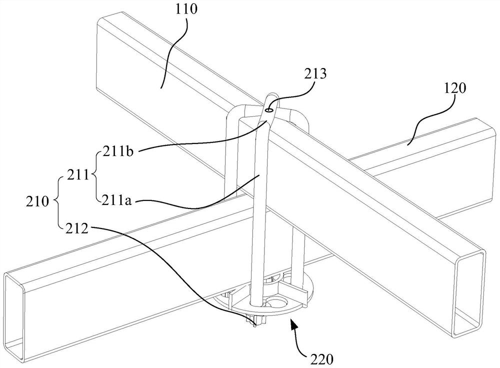
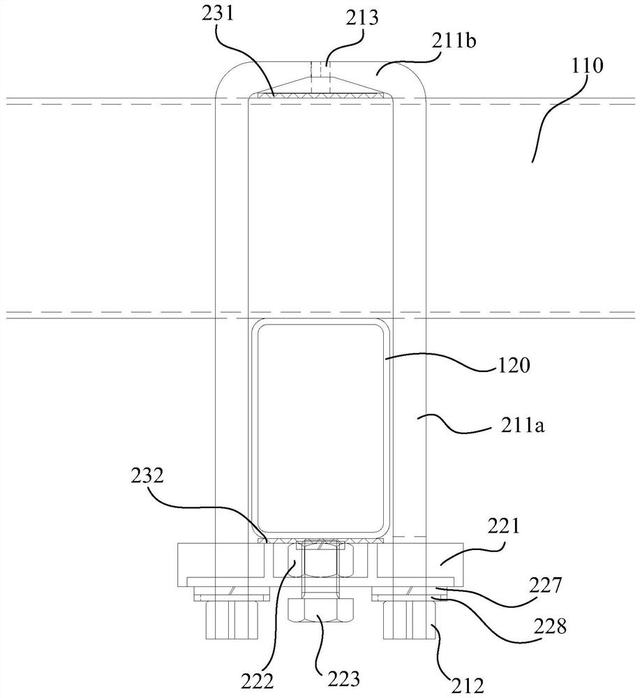
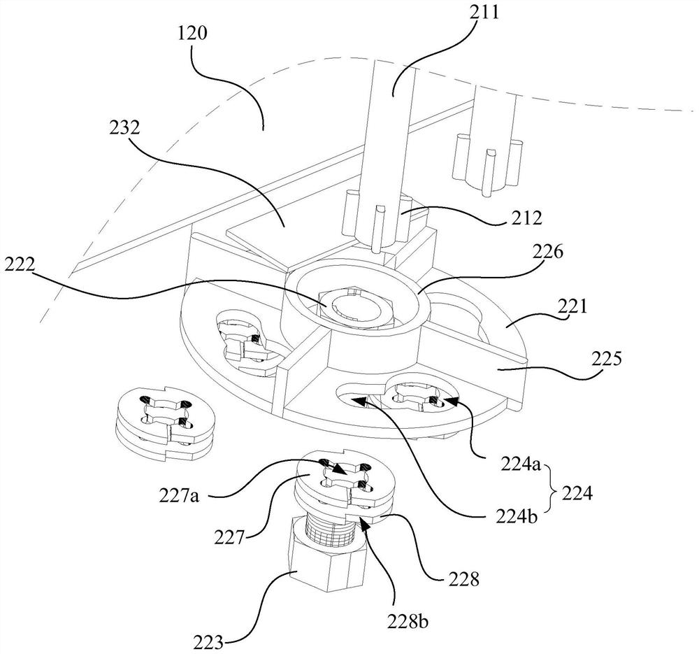
The present application provides a connection structure of cross bars, which is used at the node of the first bar and the second bar of the cross overlap, including the following components: the connecting claw includes a plurality of claw arms; each claw arm The first connecting end is located on the end face of the first rod away from the second rod, and a plurality of first connecting ends are movably connected at one place; the second connecting end of the claw arm protrudes from the second rod and is adjacent to the second rod. The two connecting ends are protrudingly provided with a number of limiting parts; the bolt assembly includes a nut plate, a nut on the nut plate, and an adjusting bolt that is screwed to the nut. The hole, the limiting part abuts against the bottom surface of the nut plate away from the second rod, and the first rod and the second rod are limited and clamped between the first connecting end of the claw arm and the adjusting bolt. The technical solution of the present application can conveniently and quickly realize the fixed connection of the cross bars without opening holes.

Description

technical field [0001] The present application belongs to the technical field of fasteners, and more specifically relates to a connecting structure of cross bars. Background technique [0002] At present, in the photovoltaic support, the materials are mostly steel, aluminum, FRP (Fiber Reinforced Polymer fiber reinforced composite material) composite materials, etc. Among them, due to cost considerations, steel is still the first choice for the support material. However, the connection of steel rods, especially the connection at the intersection joints of the rods, usually requires drilling holes and passing bolts on the rods. Although steel can be anti-corrosion through surface treatment, in the actual construction process, the perforation position is often bumped due to sharp corners and improper operation, and the anti-corrosion layer on the surface of the hole wall is worn off. Secondary anti-corrosion work, but the poor construction environment on site and the differen...

Claims


Application Information

Patent Timeline
Patent Type & Authority Patents(China)
IPC IPC(8): F16B7/04H02S20/30
CPCF16B7/0493H02S20/30Y02E10/50
Inventor 毛惠洁张玲罗多曾得雄黄亚星钟华锋彭成泉刘富民洪桂祥
Owner ZHUHAI SINGYES RENEWABLE ENERGY TECH
Why Eureka
Try Eureka