Bearing and sealing device
A sealing device and main sealing technology, applied in bearing components, shafts and bearings, engine sealing, etc., can solve the problems of high fuel consumption, unfavorable energy saving, etc., and achieve the effects of reducing wear, avoiding internal air pressure drop, and reducing fuel consumption
- Summary
- Abstract
- Description
- Claims
- Application Information
AI Technical Summary
Problems solved by technology
Method used
Image

Examples
Embodiment Construction
[0031] It can be seen from the background art that the oil consumption of the sealing device is large, which is not conducive to saving energy.
[0032] Combine below figure 1 Analyze the reasons for the high oil consumption of the sealing device.
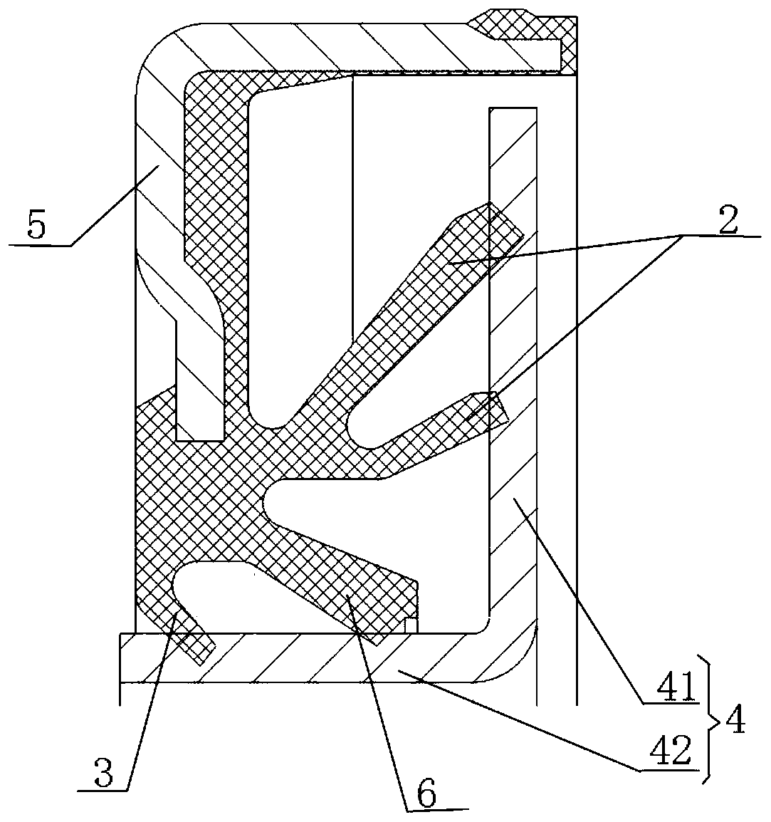
[0033] figure 1 Is a schematic diagram of a sealing device.
[0034] Such as figure 1 As shown, a sealing device includes: a skeleton 5, a dustproof ring 4, a sealing lip is fixed on the skeleton 5, and the sealing lip includes a dustproof lip 3, a main sealing lip 6 and a centrifugal lip 2. In order to ensure good sealing performance, The sealing lip and the dustproof ring 4 are in interference contact, the main sealing lip 6 and the dustproof lip 3 are closely attached to the axial part 42 of the dustproof ring 4, and the centrifugal lip 2 is closely fitted to the radial part 41 of the dustproof ring 4 , During the rotation of the sealing device, the frictional torque between the sealing lip and the dustproof ring is relative...
PUM
 Abstract
Description
Claims
Application Information