

Slide bearing
A sliding bearing and relatively sliding technology, which is applied in the direction of sliding contact bearings, bearings, and rotating bearings, etc., can solve the problems of increased friction torque, unsatisfactory design, and increased wear design, etc., to achieve excellent assembly and simple structure , The effect of long bearing life
Inactive Publication Date: 2012-07-04
NTN CORP
View PDF6 Cites 7 Cited by
- Summary
- Abstract
- Description
- Claims
- Application Information
AI Technical Summary
Problems solved by technology
However, this resin sliding bearing also has a problem that the frictional moment is about 2 to 5 times higher than that of the deep groove ball bearing.
In particular, when the roughness of the bearing sliding surface of the heating roller is rough, there is a problem that the frictional moment becomes larger and wear becomes larger at the same time, which cannot satisfy the design.
Method used
View moreImage
Smart ImageViewing Examples

Examples
Embodiment 1~ Embodiment 3、 comparative example 1 and comparative example 2
[0074] Prepare synthetic resin, sintered metal, fluorine grease, and grease retaining recess shown in Table 1. Inner ring inner diameter φ25mm (convex curvature R15.5mm), outer ring outer diameter φ37mm (concave curvature R15.5mm), and width 7mm Sliding bearing test piece ( figure 1 plain bearing shown). This test piece was subjected to the friction and wear test shown below, and the coefficient of dynamic friction was measured. The results are written down in Table 1 together. In addition, the amount of grease in Examples 2, 3, and Comparative Example 2 was 1 g.
Login to View More PUM
 Abstract
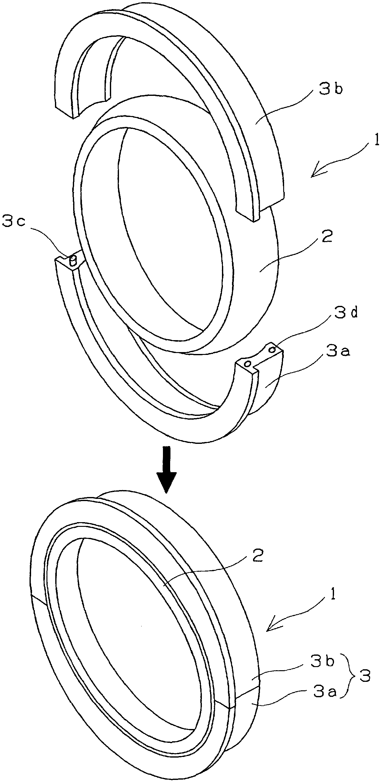
A slide bearing having a simple configuration and low friction torque. A slide bearing (1) for supporting heat rollers, such as a fixing roller and a pressing roller which are used for an image forming device, the slide bearing (1) comprising an outer ring (3) and an inner ring (2). Either the outer ring (3) or the inner ring (2) consists of resin, and the other consists of a sintered metal. The outer peripheral surface of the inner ring (2) is a convex surface, and the inner peripheral surface of the outer ring (3) is a concave surface corresponding to the convex surface. The outer ring (3) is bisected in the radial direction, and the inner ring (2) is sandwiched between the bisected halves of the outer ring (3). The inner peripheral surface of the outer ring (3) and the outer peripheral surface of the inner ring (2) are in sliding contact with each other.
Description
technical field [0001] The present invention relates to a sliding bearing, and more particularly, to a sliding bearing used for supporting heated rollers (heat rollers) such as fixing rollers and pressure rollers of fixing devices of image forming apparatuses such as copiers, printers, and facsimile machines. Background technique [0002] Generally, in the fixing device of an image forming apparatus, a toner is attached to an electrostatic latent image formed by an optical device, the toner image is transferred to a copy paper, and the image is fixed. In this fixing process, the toner image is passed between a fixing roller with a built-in heater and a pressure roller. Thereby, the transfer image composed of the toner image is fused to the copy paper by heat fusion. [0003] The fixing roller is made of soft metal with a wire-shaped or rod-shaped heater installed in the shaft center portion, and is formed into a cylindrical shape in which a shaft portion with a small diamet...
Claims
Login to View More Application Information
Patent Timeline
 Patent Type & AuthorityApplications(China)
IPC IPC(8): F16C33/10F16C13/02F16C17/02F16C33/20G03G15/20H05B3/00
CPCF16C33/102F16C33/20F16C13/02F16C17/022F16C33/128G03G15/2053F16C23/046F16C33/201F16C2240/44
Inventor冲芳郎福泽觉广濑和夫
OwnerNTN CORP