Motor-driven parking brake apparatus

a technology of parking brakes and brakes, which is applied in the direction of braking systems, apparatus for force/torque/work measurement, instruments, etc., can solve the problem of increasing the size of the load sensor, and achieve the effect of suppressing the occurrence of situations and increasing the accuracy of release determination

Inactive Publication Date: 2011-02-22
ADVICS CO LTD
View PDF15 Cites 8 Cited by
  • Summary
  • Abstract
  • Description
  • Claims
  • Application Information

AI Technical Summary

Benefits of technology

[0007]The present invention has been accomplished in order to solve the above-described problem, and an object of the present invention is to provide a motor-driven parking brake apparatus which can reduce the size of a load sensor.
[0010]When the elastic member accommodated within the accommodation member receives a certain load via a predetermined surface thereof, the ratio between the magnitude of the certain load and the magnitude of the load which is transmitted to the outside from the exposed portion of the elastic member exposed from the opening (not facing the predetermined surface) of the accommodation member tends to be equal to the ratio between the area of the predetermined surface and the area of the opening. Accordingly, the above-described configuration enables the load sensor to detect the load received from the exposed portion, which is a portion of the total load and proportional to the total load, by making use of the above-described tendency produced by the elastic member.
[0011]In the motor-driven parking brake apparatus according to the present invention, preferably, a bearing for reducing frictional torque which the shaft member receives due to rotation of the shaft member is disposed between the predetermined surface of the elastic member and the other end of the shaft member. This configuration reduces a drop in drive efficiency of the electric motor stemming from the frictional torque which the shaft member receives due to rotation of the shaft member.
[0013]The load sensor may be a displacement sensor which detects an amount by which the exposed portion of the elastic member projects into the opening due to deformation of the exposed portion. When the elastic member receives the total load, the exposed portion projects into the opening due to deformation of the exposed portion. The amount of projection (hereinafter referred to “projection amount”) of the exposed portion of the elastic member tends to be proportional to the total load, and accordingly, proportional to a portion of the total load. Therefore, the above-described configuration enables a portion of the total load to be detected through detection of the projection amount.
[0018]Accordingly, the “displacement change rate” for the case where the total load is less than the predetermined value can be set to be greater than that for the case where the total load is equal to or greater than the predetermined value. By virtue of this configuration, for example, in the case of determining whether or not to end a control of bringing the parking brake from a braking state to a release state (hereinafter, this determination will be referred to as “release determination”) is performed through detection that the movable member has reached a position corresponding to decrease of the total load to a predetermined, small value (which is smaller than the predetermined value and approximately zero), the accuracy of the release determination can be increased. As a result, it is possible to suppress occurrence of a situation where relatively large cable tension remains after the release determination (so-called dragging of the brake).

Problems solved by technology

Therefore, the motor-driven parking brake apparatus has a problem in that the size of the load sensor must be increased in order to secure the strength of the load sensor.

Method used


Image

  • Motor-driven parking brake apparatus
  • Motor-driven parking brake apparatus
  • Motor-driven parking brake apparatus

Examples


first embodiment

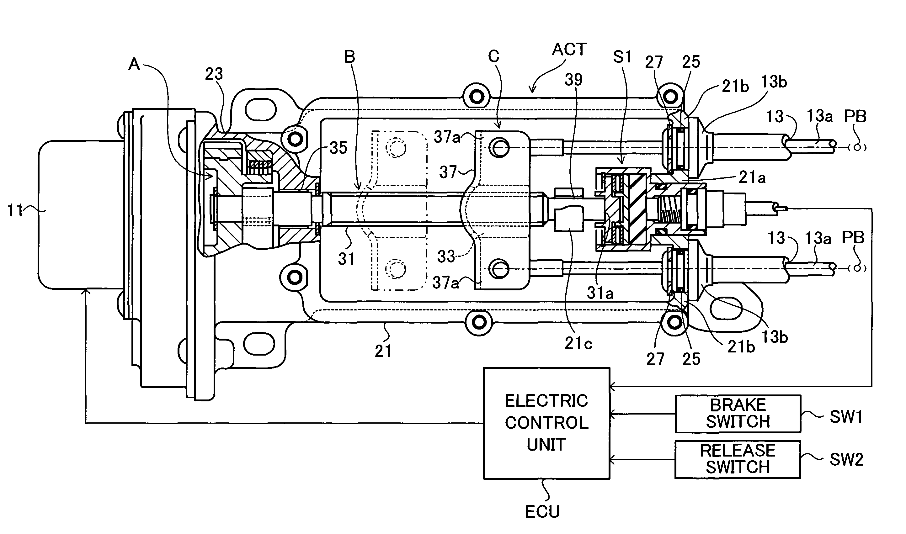
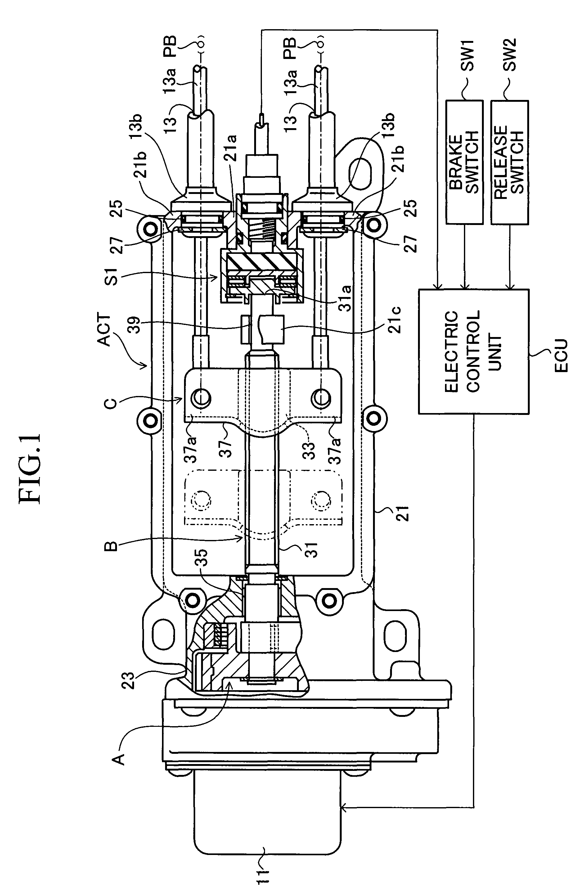
[0027]FIG. 1 shows a motor-driven parking brake apparatus for an automobile according to a first embodiment of the present invention. This motor-driven parking brake apparatus includes an actuator section ACT, a pair of parking brakes PB driven by the actuator section ACT, and an electric control unit ECU which controls the actuator section ACT. The actuator section ACT includes a speed reduction mechanism A for transmitting rotational drive torque of an electric motor 11, while reducing the rotational speed; a conversion mechanism B for converting rotational motion, transmitted by the speed reduction mechanism A, into translational motion; an equalizer mechanism C which distributes force produced by the translational motion to two output portions; a pair of cables 13 whose first ends are connected to the corresponding output portions of the equalizer mechanism C and whose second ends are connected to the corresponding parking brakes PB; and a pressure sensor S1 (load sensor) which ...

second embodiment

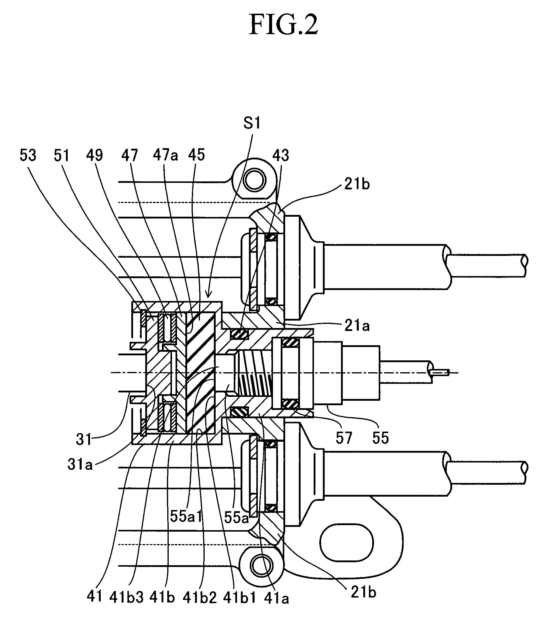
[0049]Next, a motor-driven parking brake apparatus according to a second embodiment of the present invention will be described. This second embodiment differs from the first embodiment only in the point that in place of the pressure sensor S1, a displacement sensor S2 is used as a load sensor for detecting the axial load of the screw shaft 31. Hereinbelow, only the point of difference will be described with reference to FIG. 4, which is an enlarged view of the displacement sensor S2. In FIG. 4, members and portions identical with or equivalent to those shown in FIG. 2 are denoted by like reference numerals, and their descriptions will not be repeated. For each of the axially movable members shown in FIG. 4, a corresponding axial position in a state shown in FIG. 4 (when the total load F is zero) is referred to as “original position.”

[0050]A spool 61 (movable member), which assumes the form of a stepped cylindrical tube and has a larger diameter portion 61a, a flange portion 61b, and...

third embodiment

[0061]Next, a motor-driven parking brake apparatus according to a third embodiment of the present invention will be described. This third embodiment differs from the second embodiment only in the point that in place of the displacement sensor S2, a displacement sensor S3 is used as a load sensor for detecting the axial load of the screw shaft 31. Hereinbelow, only the point of difference will be described with reference to FIG. 5, which is an enlarged view of the displacement sensor S3. In FIG. 5, members and portions identical with or equivalent to those shown in FIG. 4 are denoted by like reference numerals, and their descriptions will not be repeated. For each of the axially movable members shown in FIG. 5, a corresponding axial position in a state shown in FIG. 5 (when the total load F is zero) is referred to as “original position.”

[0062]In the cylindrical columnar interior space of the cylindrical cup portion 41b of the casing 41 of the displacement sensor S3, a ring-shaped was...


PUM


Abstract

A motor-driven parking brake apparatus includes a load sensor (pressure sensor) for detecting axial load of a screw shaft. The pressure sensor includes a transmission member which receives the axial load via a circular surface of a plate, and a casing which accommodates the transmission member and receives the axial load via the transmission member. This casing has a circular opening having an opening area smaller than the surface of the circular surface. The pressure sensor detects a pressure generated due to a load received from an exposed portion of the transmission member which is exposed from the circular opening. Due to characteristics of the transmission member, the load received from the exposed portion is a portion of the axial load and proportional to the axial load.

Description

CROSS REFERENCE TO RELATED APPLICATION[0001]This application is based on and claims under 35 U.S.C. sect, 119 with respect to Japanese Patent Application No. 2006-227472 filed on Aug. 24, 2006, the entire content of which is incorporated herein by reference.BACKGROUND OF THE INVENTION[0002]1. Field of the Invention[0003]The present invention relates to a motor-driven parking brake apparatus, and is applicable to, for example, a parking brake apparatus for a vehicle.[0004]2. Description of the Related Art[0005]Japanese Patent Application Laid-Open (kokai) No. 2006-17158 discloses a motor-driven parking brake apparatus which includes an electric motor; a shaft member which rotates about its axis upon receipt of rotational drive torque of the motor through one end of the shaft member; a conversion mechanism which converts rotational motion of the shaft member to translational motion of a translational movement portion; a cable having a first end connected to the translational movement ...

Claims


Application Information

Patent Timeline
Patent Type & Authority Patents(United States)
IPC IPC(8): F16D66/00F16D65/28
CPCB60T11/046B60T13/746
Inventor TSUBOUCHI, KAORU
Owner ADVICS CO LTD
Why Eureka
Try Eureka