Field torque calibration device

A calibration device and on-site technology, applied in the direction of measuring devices, force/torque/power measuring instrument calibration/testing, instruments, etc., can solve problems that affect the accuracy of calibration results, cannot achieve pure torque loading, and sensor output shaft bending , to achieve the effect of easy maintenance and replacement, wide application range and reduction of system errors

Inactive Publication Date: 2016-12-07
BEIJING AEROSPACE PROPULSION INST
View PDF12 Cites 8 Cited by
  • Summary
  • Abstract
  • Description
  • Claims
  • Application Information

AI Technical Summary

Problems solved by technology

However, this method will affect the accuracy of the calibration results. The main reasons are as follows: the torque sensor carrying a large torque needs a weight corresponding to a relatively large weight for torque calibration, and the support point of the output shaft of the torque sensor is not in the same plane as the gravity of the weight. The radial force formed by the static calibration beam and the weight of the weight has a bending effect on the output shaft of the sensor, and pure torque loading cannot be achieved; the static calibration beam needs to be kept in a horizontal state during calibration, and it is difficult to judge the horizontal position, and the inclined static calibration beam will The length of the effective arm has an impact; the lever needs to return to a balanced state, and the configuration of a leveling device to adjust the balance of the lever will make the structure of the calibration device more complicated
In addition, the friction torque at the lever support part of the arm will reduce the accuracy of the calibration device

Method used


Image

  • Field torque calibration device
  • Field torque calibration device
  • Field torque calibration device

Examples


Embodiment Construction

[0027] In order to make the solution of the present invention clearer, the present invention will be further described below in conjunction with the accompanying drawings and specific embodiments:

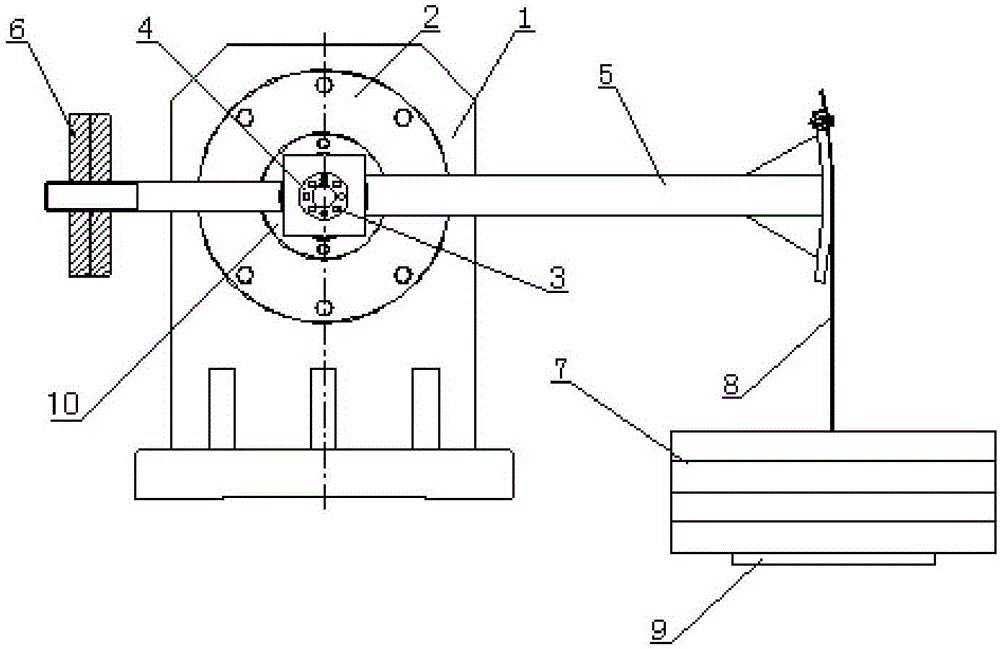
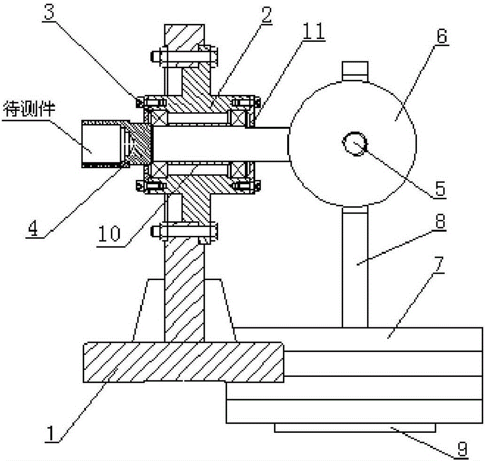
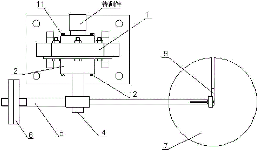
[0028] like Figure 1-3 As shown, an on-site torque calibration device includes a support 1, a support sleeve 2, a bearing 3, a positioning shaft 4, a static calibration beam 5, a balance plate 6 and a weight 7; 4, the supporting sleeve 2, the positioning shaft 4 is matched with the bearing 3 and installed in the supporting sleeve 2, one end of the positioning shaft 4 is connected with the workpiece to be tested, and the other end of the positioning shaft 4 is fixedly connected with the static calibration beam 5, and the static calibration beam 5 A weight 7 is suspended at one end, and a balance plate 6 for adjusting balance is installed at the other end of the static calibration beam 5 .

[0029] The support 1 adopts a cubic structure, and the middle part of the support 1 is prov...


PUM


Abstract

The invention discloses a field torque calibration device. The field torque calibration device comprises a support, a supporting sleeve, bearings, a positioning shaft, a static correction beam, a balance disc and weights. The supporting sleeve used for installing the positioning shaft is arranged on the support, the positioning shaft and the bearings are installed in the supporting sleeve in a matched mode, one end of the positioning shaft is connected with a part to be measured, and the other end of the positioning shaft is fixedly connected with the static correction beam; the weights are hung at one end of the static correction beam, and the balance disc is installed at the other end of the static correction beam. According to the field torque calibration device, the two rows of rolling bearings are adopted as supporting of the positioning shaft, bending moment caused by self-weight of the weights is eliminated, friction moment of the supporting part is reduced, and the problem that pure torque loading can not be carried out on a large torque sensor is solved; the balance disc is installed at one end of the static correction beam, a circular arc structure is arranged at the other end of the static correction beam, and the problem that when the static correction beam is inclined, the length of a force arm is changed is solved; by adopting a thin steel strip to hang the weights, it is ensured that the action force arm of the gravity of the weights is located on the horizontal line all the time, system errors of the device are reduced, and the sensitivity of the device is improved.

Description

technical field [0001] The invention relates to an on-site torque calibration device, which is especially suitable for measuring and testing various torque sensors and torque measuring equipment, and belongs to the technical field of torque calibration of rotating machinery. Background technique [0002] Torque is an important mechanical characteristic parameter in rotating machinery. As a torque measuring device, torque sensors are widely used in power machinery torque measurement. Large-scale high-speed rotating machinery requires high coaxiality and difficult adjustment. In order to minimize the disassembly and assembly of the torque meter, and to ensure the consistency of the use state, it is necessary to measure and calibrate the torque sensor on site. [0003] At present, the measurement and calibration of torque sensors mostly adopts torque static calibration. The more mature method is to add a certain number of weights to a fixed static calibration beam, and generate...

Claims


Application Information

Patent Timeline
Patent Type & Authority Applications(China)
IPC IPC(8): G01L25/00
CPCG01L25/003
Inventor 王洋洲丁振晓尹健昭刘倩苏卫民郭慧孙大洪
Owner BEIJING AEROSPACE PROPULSION INST
Why Eureka
Try Eureka