Spiral guide machine head body structure

A screw-type, machine-head technology, applied in the field of firearms, can solve problems such as poor smoothness of opening and closing, difficult to ensure consistency of processing technology, complex structure, etc., and achieve balance of force, damage, improvement of projectile accuracy, and excellent structure. Effect

Pending Publication Date: 2020-06-12
CHONGQING JIANSHE IND GRP
View PDF0 Cites 1 Cited by
  • Summary
  • Abstract
  • Description
  • Claims
  • Application Information

AI Technical Summary

Problems solved by technology

[0003] The purpose of the present invention is to provide a screwdriver to solve the problems in the prior art, such as the tensile and compressive stress caused by the bending moment on the machine head body when the bolt is opened and locked, the smoothness of the opening and closing action, the complex structure, and the difficulty in ensuring the consistency of the processing technology. Type-guided nose body structure, by improving the force condition of the current rotary locking mode nose body, improving the smoothness of entering the bore, opening and closing, optimizing the structure and process

Method used


Image

  • Spiral guide machine head body structure
  • Spiral guide machine head body structure
  • Spiral guide machine head body structure

Examples


Embodiment Construction

[0024] The working principle and structure of the present invention will be further described in detail below in conjunction with the embodiments and drawings.

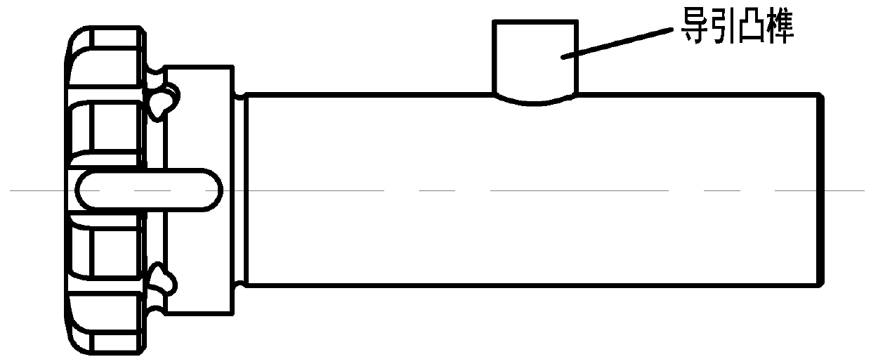
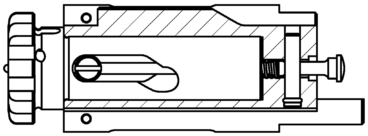
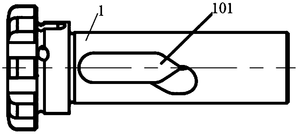
[0025] Such as Figure 2-Figure 5 As shown, a spiral guide head body structure includes a firing pin 6, a firing pin spring 4 sleeved on the firing pin 6, a frame 2, a firing pin 5 connecting the firing pin 6 and the frame 2, The machine head rotating pin 3 and the machine head body 1, the machine head rotating pin 3 is provided with a through hole through which the firing pin 6 passes, and the top of the front end of the machine frame 2 is radially provided for the machine head rotating pin 3 to pass through The through hole 201 of the machine frame 2 is provided with a central through hole along the axial direction. The through hole 201 and the central through hole pass through. The rear end of the machine frame 2 is provided with a through hole for the striker pin in the radial direction. Pin hole 202; at the front e...


PUM


Abstract

The invention discloses a spiral guide machine head body structure. The spiral guide machine head body structure comprises a firing pin, a firing pin spring, a machine frame, a firing pin pin, a machine head rotating pin and a machine head body, wherein a first through hole is formed in the machine head rotating pin, a second through hole allowing the machine head rotating pin to penetrate throughis formed in the top of the front end of the machine frame in the radial direction, a center through hole is formed in the machine frame and communicates with the through holes, a pin hole is formedin the rear end of the machine frame in the radial direction, the machine head body is arranged at the front end of the machine frame, locking teeth are arranged at the front end of the machine head body, guide spiral grooves are formed in the circumferential direction of the rear end of the machine head body and are symmetrically arranged along the center of the machine head body, a center through hole allowing the firing pin to penetrate through is formed in the machine head body in the axial direction, and the guide spiral grooves communicate with the center through hole, the machine head body extends into the central through hole of the machine frame and is connected with the machine frame through the machine head rotating pin, the machine head rotating pin moves in the guide spiral grooves to drive the machine head body to complete unlocking and locking actions, and the firing pin penetrates through the machine frame, the machine head rotating pin and the central hole of the machine head body to be connected into a whole.

Description

Technical field [0001] The invention relates to the technical field of firearms, in particular to a screw-guided nose body structure. Background technique [0002] For the current general automatic and semi-automatic firearms, many of the machine head rotary locking structures are adopted. They arrange and process spiral grooves on the machine frame and process the guide tenon on the machine head body (as shown in 1), The tenon fits into the guide groove, so that the head body moves and rotates along the spiral groove of the machine frame under the drive of the machine frame to realize the opening and closing action. This layout form adds a guiding tenon on the tail end of the nose body. During the opening and closing process, the spiral groove of the machine frame exerts a backward force on the nose body. The center) is not collinear, so that the head body bears the tensile and compressive stress generated by the bending moment (as shown in 6). At the same time, each locking to...

Claims


Application Information

Patent Timeline
Patent Type & Authority Applications(China)
IPC IPC(8): F41A9/38
CPCF41A9/38
Inventor 胡永勇沈潇龚会黄宜民武旭飞唐成刚王太平彭璐朱应秋
Owner CHONGQING JIANSHE IND GRP
Why Eureka
Try Eureka