
Fault detection method, device, device and storage medium for electro-pneumatic equipment

A technology for pneumatic equipment and fault detection, applied in measurement devices, neural learning methods, mechanical valve testing, etc., can solve the problems of low fault location accuracy and low fault detection efficiency, and achieve the effect of improving detection efficiency and accuracy.

Active Publication Date: 2022-02-22
北京昊鹏智能技术有限公司
View PDF8 Cites 0 Cited by
  • Summary
  • Abstract
  • Description
  • Claims
  • Application Information

AI Technical Summary

Problems solved by technology

[0005] Embodiments of the present invention provide a fault detection method, device, device, and storage medium for electro-pneumatic equipment to solve the problems of low fault detection efficiency and low fault location accuracy caused by manual detection of equipment faults in the prior art question

Method used


Image

  • Fault detection method, device, device and storage medium for electro-pneumatic equipment
  • Fault detection method, device, device and storage medium for electro-pneumatic equipment
  • Fault detection method, device, device and storage medium for electro-pneumatic equipment

Examples


Embodiment Construction

[0049]In order to make the purposes, technical solutions and advantages of the embodiments of the present invention clearer, the technical solutions in the embodiments of the present invention will be clearly and completely described below with reference to the accompanying drawings in the embodiments of the present invention. Obviously, the described embodiments It is only a part of the embodiments of the present invention, but not all of the embodiments. Based on the embodiments of the present invention, all other embodiments obtained by those of ordinary skill in the art without creative efforts shall fall within the protection scope of the present invention.

[0050] The terms "first", "second", "third", "fourth", etc. (if present) in the description and claims of the present invention and the above-mentioned drawings are used to distinguish similar objects and are not necessarily used to Describe a particular order or sequence. It is to be understood that the data so use...


PUM


Abstract

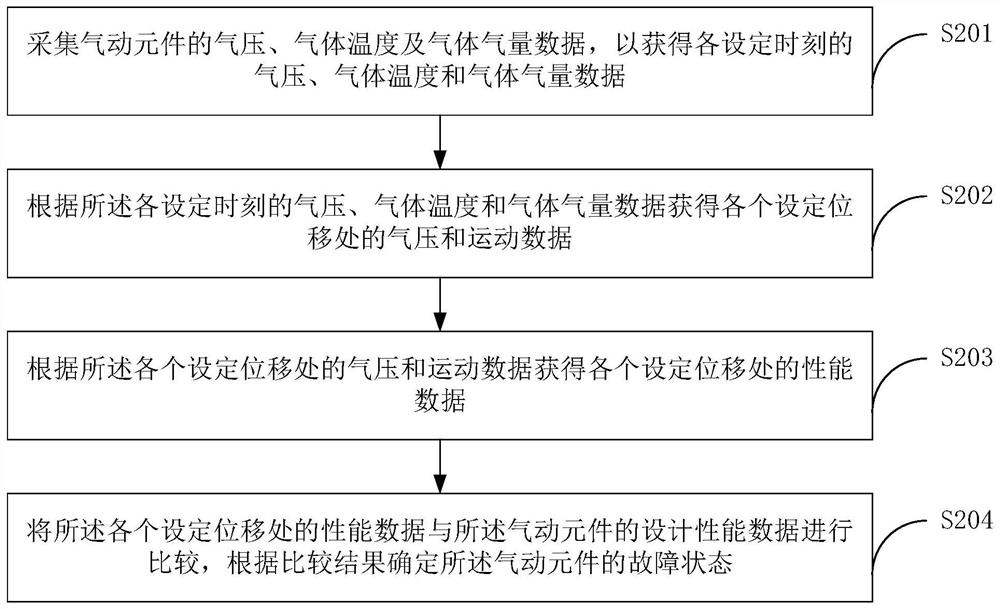
Embodiments of the present invention provide a fault detection method and device for electro-pneumatic equipment. The method includes: collecting air pressure, gas temperature, and gas volume data of pneumatic components at each set time; The gas temperature and gas volume data are converted to the air pressure and motion data at each set displacement; then the performance data at each set displacement is calculated by using the air pressure and motion data at each set displacement, so that the The performance data is compared with the design performance data to determine the health state of the pneumatic components. Compared with the existing manual detection method, this method can detect the fault state in time and provide a basis for the operation of the electro-pneumatic equipment. In addition, this method can also realize fault prediction.

Description

technical field [0001] Embodiments of the present invention relate to the technical field of electro-pneumatic equipment, and in particular, to a fault detection method, device, equipment and storage medium for electro-pneumatic equipment. Background technique [0002] Electronically controlled pneumatic equipment is an important equipment widely used in rail transportation, manufacturing, mining, oil and gas extraction, chemical industry, water supply and drainage, and environmental protection. In addition, the control mode of the electro-pneumatic equipment is electronic control, and the driving mode is pneumatic. For example, electro-pneumatic valves are important components of various pipelines, and their main structures include pneumatic components (such as cylinders), pistons or diaphragms, springs, pneumatic rods, and connections between pneumatic rods and loads (such as valves). Its working principle is that when the electro-pneumatic valve receives the valve openin...

Claims


Application Information

Patent Timeline
Patent Type & Authority Patents(China)
IPC IPC(8): G01M13/003G01D21/02G06N3/04G06N3/08
CPCG01M13/003G01D21/02G06N3/04G06N3/08
Inventor 李鲲鹏陈飞李祎璞
Owner 北京昊鹏智能技术有限公司
Learn More