A Measurement Method Based on Visual Array Antenna

A technology of an array antenna and a measurement method, which is applied to a radio wave measurement system, a direction finder using radio waves, a measurement device, etc., can solve the problems of difficulty in precise positioning, difficult to achieve effective positioning, separation of coupling components, etc.

Active Publication Date: 2022-03-18
ZHEJIANG UNIV
View PDF7 Cites 0 Cited by
  • Summary
  • Abstract
  • Description
  • Claims
  • Application Information

AI Technical Summary

Problems solved by technology

However, these methods have certain limitations in the application process
For example, when the coupling effect between array antenna elements is large, it is difficult for the above positioning method to separate the coupling components, which brings great difficulties to precise positioning
In addition, in a complex environment, electromagnetic waves are reflected by buildings, the ground, trees, etc., making the signals received by the array antenna have multipath effects, making it more difficult to achieve effective positioning

Method used


Image

  • A Measurement Method Based on Visual Array Antenna
  • A Measurement Method Based on Visual Array Antenna
  • A Measurement Method Based on Visual Array Antenna

Examples


Embodiment 1

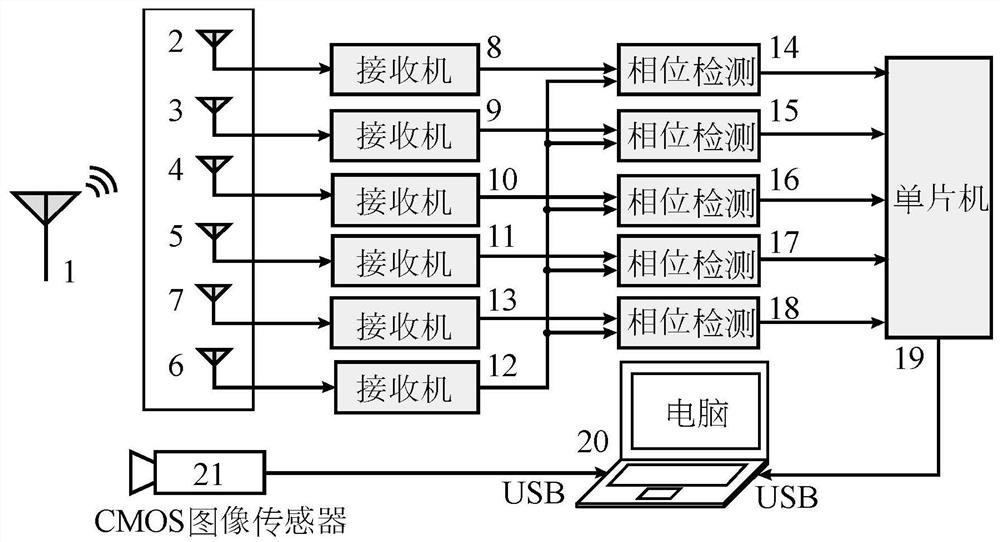
[0058] Embodiment 1 adopts figure 1 , figure 2 and image 3 The direction finding system shown demonstrates the first method of direction finding.

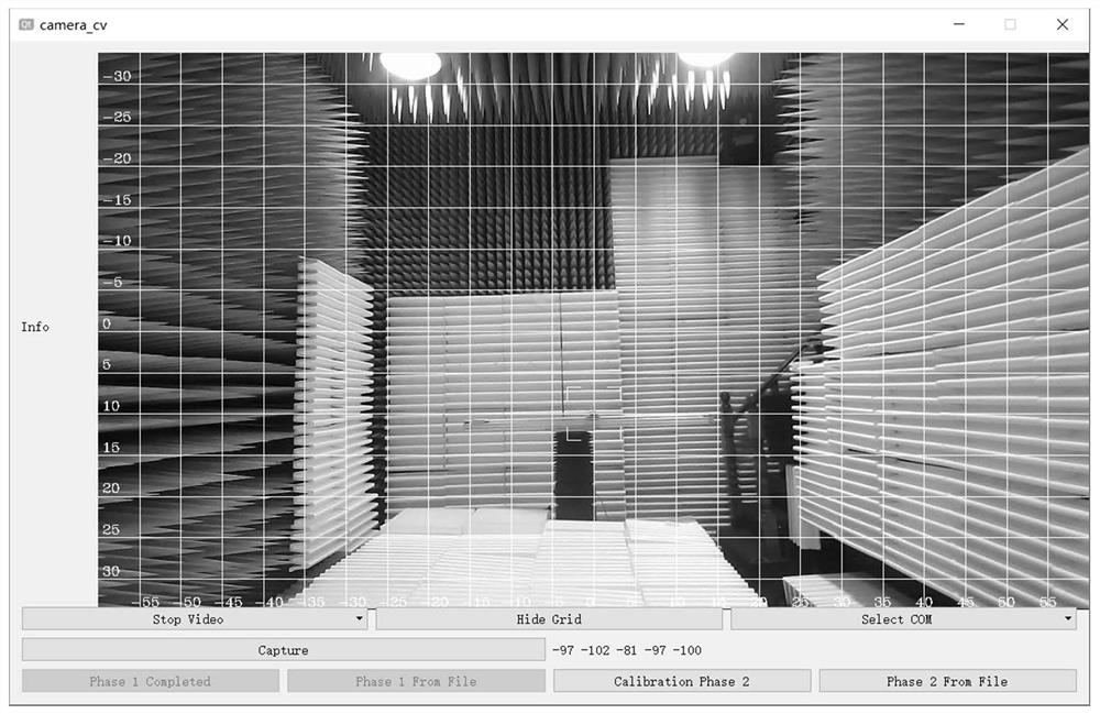
[0059] image 3 The software calibration platform shown also has direction finding capabilities. After obtaining the calibration data corresponding to all grid points, when using the software calibration platform for actual positioning, whenever the signal source moves to a certain image position, the signal phase detection system automatically detects the phase difference information, as shown in the figure -97 102 -81 -97 -100. The measured phase difference information and all the phase difference information in the calibration data are calculated one by one using the correlation coefficient formula. When the calculated correlation coefficient is the largest, the corresponding viewing angle coordinates is the image position where the signal source is located, such as image 3 The position indicated by the square cursor i...

Embodiment 2

[0061] Embodiment 2 adopts figure 1 , figure 2 and image 3 The direction finding system shown and Figure 4 The shown neural network structure demonstrates the second direction finding method.

[0062] After obtaining the calibration data corresponding to all grid points, the backpropagation algorithm can be used to optimize the establishment of Figure 4 The neural network shown. The input of the neural network is the phase difference information, and the output is the viewing angle coordinates The calculated value of . Figure 4 The operation process from left to right can be regarded as the forward propagation process of the neural network. In the forward propagation process, the phase difference information is input, and the calculated viewing angle coordinates for output. In this embodiment, the backpropagation algorithm is to calculate the viewing angle coordinates based on the phase difference information of the calibration data Corresponding viewing angle c...

Embodiment 3

[0065] Embodiment 3 adopts figure 1 , figure 2 and image 3 The direction finding system shown and Figure 6 The shown neural network structure demonstrates the second direction finding method.

[0066] After obtaining the calibration data corresponding to all grid points, the viewing angle coordinates The incident angle of the electromagnetic wave signal can be obtained by using the coordinate transformation principle according to the positional relationship between the CMOS image sensor and the array antenna angle of incidence Can be used to form a complex vector I' constructed based on phase difference information as input in a neural network n and as output a complex vector V constructed based on the coordinate information n .

[0067] Figure 6 The operation process from left to right in can be regarded as the forward propagation process of the neural network. In this embodiment, the backpropagation algorithm uses the calculation error of each forward propaga...


PUM


Abstract

The invention discloses a measurement method based on a visual array antenna. The image of the signal source is taken at a fixed position by the CMOS image sensor, and the coordinate information of the signal source is obtained through image analysis and processing; the signal phase detection system based on the array antenna is used to detect the phase difference information of the receiving antenna current in real time, and finally the phase difference information and the coordinate information are used to compare Combined with the establishment of correlation relationship, the phase difference information collected by the signal source to be tested is processed by using the correlation relationship to obtain the position of the signal source, and the location measurement of the signal source is realized. The invention can realize the positioning and calibration of multiple signal source positions in the image, and can use the neural network algorithm to realize the direction finding and positioning of the signal source at any position in the image.

Description

technical field [0001] The invention discloses a signal source positioning measurement method of a visual array antenna, which involves two ways of realizing the direction finding / calibration of the visual array antenna. Background technique [0002] Traditional positioning methods include rotating or switching directional antennas, Watson-Watt direction finding, time difference of arrival (TDOA), sum and difference analysis, Doppler analysis (Doppler), and applications in more complex phased array systems and multiple Direction of Arrival (DOA) estimation methods such as Multiple Signal Classification (MUSIC), Rotation Invariance Based Signal Parameter Estimation (ESPRIT), Maximum Likelihood Estimation (MLE) in MIMO systems. However, these methods have certain limitations in the application process. For example, when the coupling effect between array antenna elements is large, it is difficult for the above positioning method to separate the coupling components, which bring...

Claims


Application Information

Patent Timeline
Patent Type & Authority Patents(China)
IPC IPC(8): G01S5/04G01S5/02G01S3/48G01S3/02G01S3/04G01C11/00
CPCG01S5/04G01S5/0257G01S5/021G01S5/0221G01S3/48G01S3/043G01S3/023G01C11/00
Inventor 王浩冉立新
Owner ZHEJIANG UNIV
Why Eureka
Try Eureka