Antenna apparatus

An antenna device and antenna technology, applied to antennas, antenna supports/mounting devices, folded antennas, etc., can solve problems such as inability to achieve better matching, deterioration of modulation accuracy and receiving sensitivity, and deterioration of communication quality, and achieve good Effects of matching, high-quality mobile communication, and stable mobile communication

Inactive Publication Date: 2003-06-25
PANASONIC CORP
View PDF1 Cites 0 Cited by
  • Summary
  • Abstract
  • Description
  • Claims
  • Application Information

AI Technical Summary

Problems solved by technology

Therefore, there will be such problems that good matching cannot be achieved in one state or two states; modulation accuracy and reception sensitivity will deteriorate and communication quality will deteriorate

Method used


Image

  • Antenna apparatus
  • Antenna apparatus
  • Antenna apparatus

Examples


Embodiment Construction

[0032] The present invention will be described in detail below with reference to the accompanying drawings.

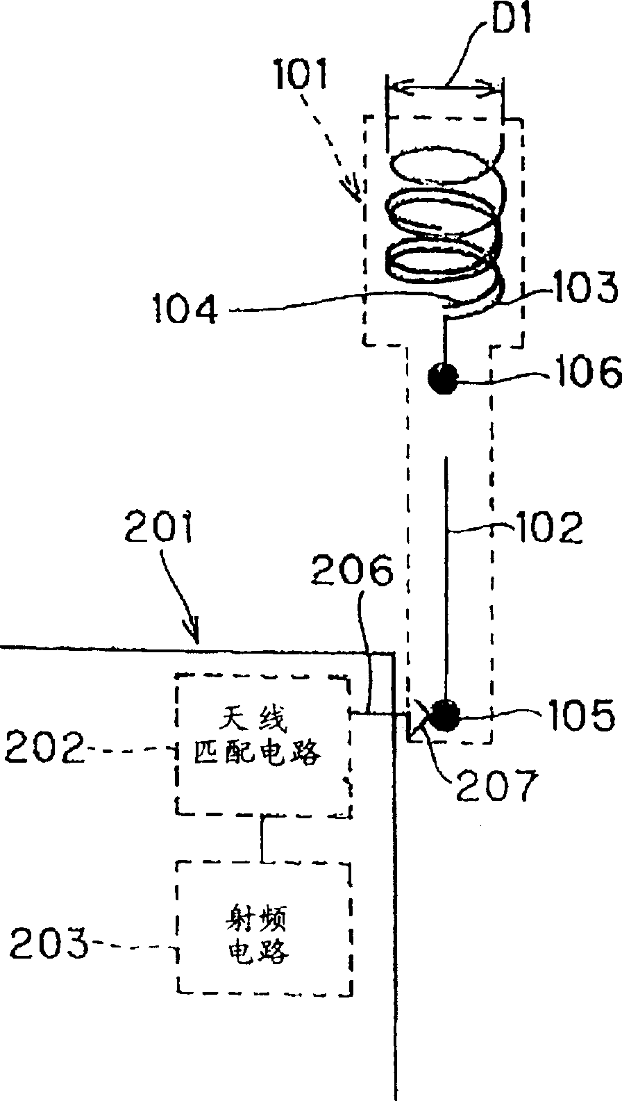
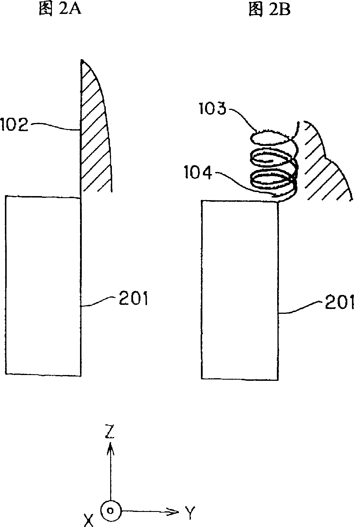
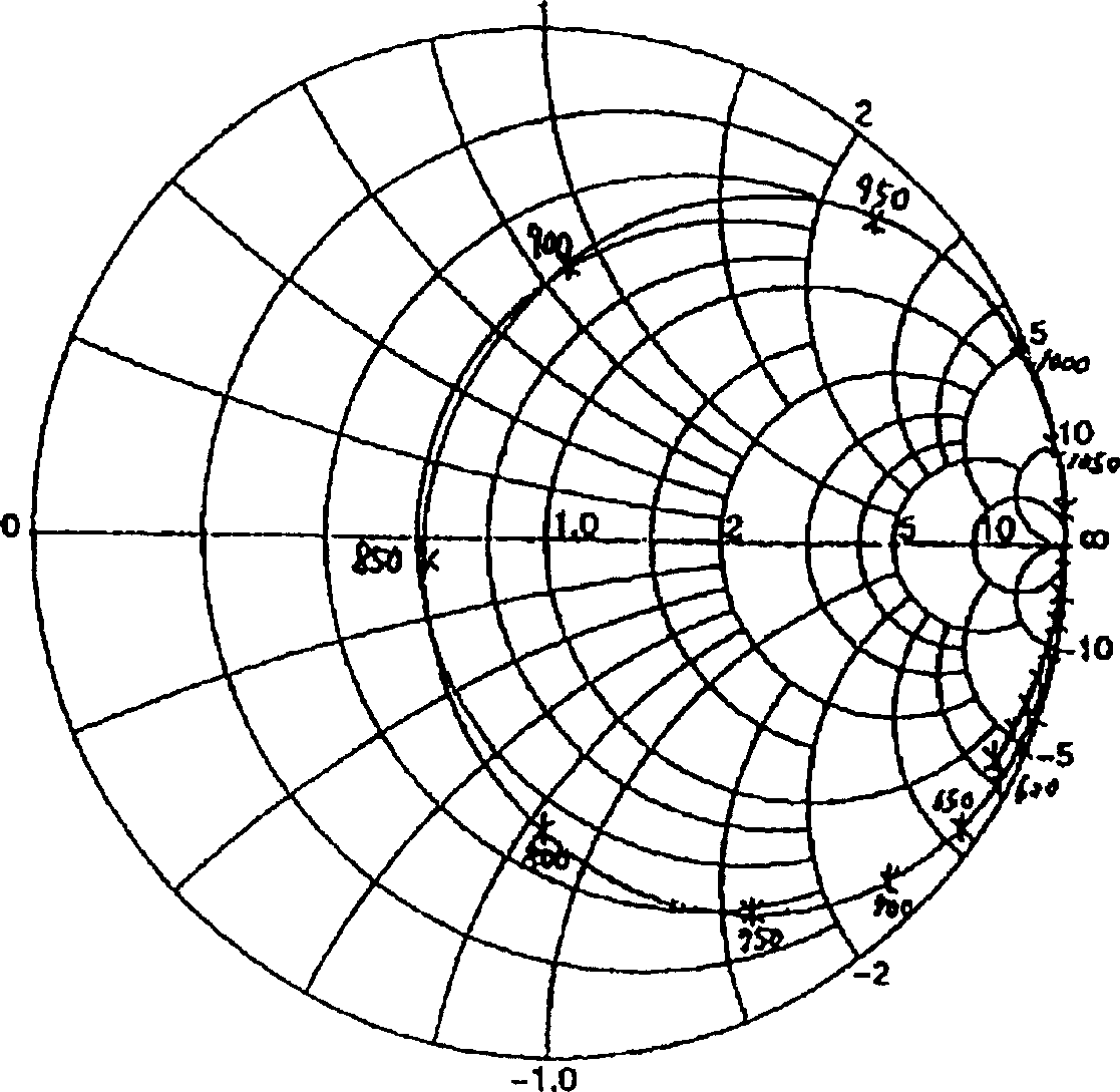
[0033] In the present invention, the impedance of the antenna element in the antenna device used in the mobile radio equipment can be adjusted by using the parasitic helical element. In addition, the impedances of the antenna unit are matched in both extended and retracted states. Therefore, its advantage is that better matching can be achieved in various frequency bands, so as to perform stable high-quality mobile communications.

[0034] The present invention provides an antenna device, which is a retractable whip antenna adapted to the first and second frequency bands used in small portable radio equipment, which includes: a monopole antenna unit, when the whip antenna is extended, the The antenna unit is connected to the antenna matching circuit through the first contact; a helical antenna unit, when the whip antenna is accommodated, the antenna unit is connected ...


PUM


Abstract

In an antenna apparatus, a monopole antenna element connected to an antenna matching circuit via a first contact 105 when a whip antenna is extended; a helical antenna element connected to the antenna matching circuit via a second contact when the whip antenna is accommodated; and a parasitic helical element disposed in close proximity to the helical antenna element at a spacing which is sufficiently small with respect to the wavelength of a first frequency band of a radio circuit.

Description

technical field [0001] The present invention relates to an antenna device mainly used in mobile radio equipment, in particular to a retractable whip antenna device, which can be used in multiple frequency bands. Background technique [0002] In recent years, the demand for mobile radio equipment, such as cellular telephones, has increased. As an antenna for mobile radio equipment, a wire whip antenna housed in a portable radio equipment has been widely used. [0003] Refer to the attached Figure 13 and 14 The structure of the antenna disclosed in Unexamined Japanese Patent Publication Hei 1-204504, which is an example of the prior art, will be described. Notice, Figure 13 and 14 This is illustrated by Figures 2 and 4 in said Japanese Patent Laid-Open Document. and, Figure 13 and 14 Reference numbers in are equivalent to those used in this reference. [0004] Such as Figure 13 As shown, when the antenna unit 14 is pulled out from the main body 10 of the telephone, t...

Claims


Application Information

Patent Timeline
Patent Type & Authority Patents(China)
IPC IPC(8): H01Q1/10H01Q1/24H01Q1/36H01Q5/10H01Q5/378H01Q9/30H01Q11/08
CPCH01Q1/244H01Q1/362H01Q1/24
Inventor 小柳芳雄小川晃一山崎正纯
Owner PANASONIC CORP
Why Eureka
Try Eureka