Resonant cavity and impedance mismatch adjusting method thereof

A technology of impedance mismatch and adjustment method, which is applied in the field of vacuum electronics, can solve the problems such as the increase of electric field inhomogeneity, achieve the effect of improving the distribution of electric field intensity and reducing the difference of impedance

Pending Publication Date: 2021-12-10
AEROSPACE INFORMATION RES INST CAS
View PDF0 Cites 0 Cited by
  • Summary
  • Abstract
  • Description
  • Claims
  • Application Information

AI Technical Summary

Problems solved by technology

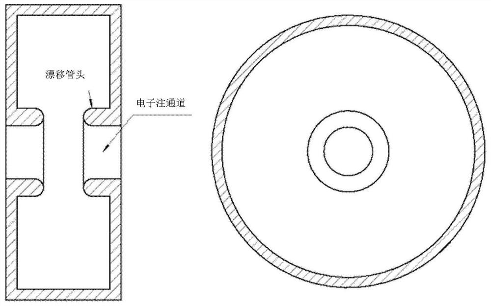
For the output resonant cavity, as the diameter of the drift tube head increases, the gap capacitance of the resonant cavity increases. In the case of maintaining a constant load quality factor, the coupling hole between the cavity and the output waveguide will cause the electron injection channels on the inner and outer layers. Increased electric field inhomogeneity
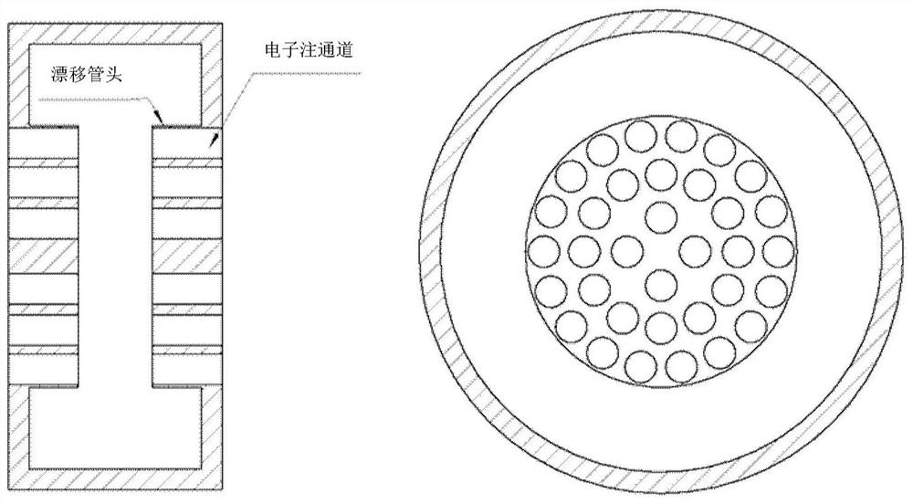
[0003] For high-power multi-beam klystrons, the use of coaxial resonators can improve the electric field inhomogeneity on the inner and outer electron beam channels; The electric field inhomogeneity on the inner and outer electron beam channels of the resonator is still very serious

Method used


Image

  • Resonant cavity and impedance mismatch adjusting method thereof
  • Resonant cavity and impedance mismatch adjusting method thereof
  • Resonant cavity and impedance mismatch adjusting method thereof

Examples


Embodiment Construction

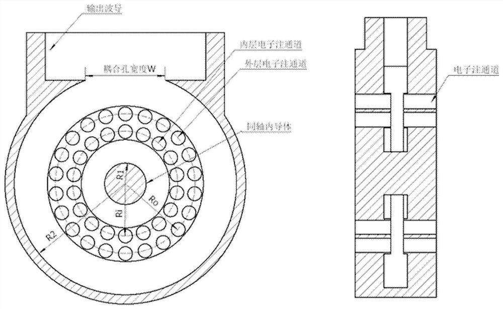
[0030] The present disclosure provides a resonant cavity and its impedance mismatch adjustment method, which can effectively adjust the impedance of the coaxial resonant cavity, reduce the difference in impedance at different electron beam positions, and improve the distribution uniformity of the electric field intensity on the electron beam channel .

[0031] In order to make the purpose, technical solutions and advantages of the present disclosure clearer, the present disclosure will be further described in detail below in conjunction with specific embodiments and with reference to the accompanying drawings.

[0032] In the process of realizing the present disclosure, the inventors found that in the existing klystrons, in order to effectively interact the high-frequency electric field in the resonant cavity with the axially moving electron beam, a double klystron with a drift tube head is usually used. In the resonant cavity, its high-frequency electric field is concentrated...


PUM


Abstract

The invention provides a resonant cavity impedance mismatch adjusting method. The method comprises the steps that the cross section of an inner conductor in a resonant cavity is set to be a ellipse; the cross section of the outer conductor in the resonant cavity is set to be a second ellipse; an adjusting pin is arranged beside the waveguide coupling hole of the resonant cavity; and the inner conductor and the outer conductor in the resonant cavity are eccentrically arranged. The invention further provides a klystron resonant cavity. The klystron resonant cavity comprises the inner conductor, an inner-layer electron beam channel, an outer-layer electron beam channel and the outer conductor from inside to outside. The cross section of the inner conductor is the first ellipse; the cross section of the outer conductor is the second ellipse; the inner conductor and the outer conductor are eccentrically arranged; and the adjusting pin is arranged beside the waveguide coupling hole of the resonant cavity.

Description

technical field [0001] The disclosure relates to the technical field of vacuum electronics, in particular to a klystron coaxial resonant cavity and a method for adjusting impedance mismatch thereof. Background technique [0002] Klystron is a microwave vacuum device that converts electron injection energy into microwave energy based on the principle of velocity modulation; its high-frequency interaction system is a separate resonant cavity, so it has high power, high gain, high efficiency and high stability Etc. As the high-frequency interaction circuit of the klystron, the resonant cavity has a decisive influence on the performance indicators such as power, efficiency, gain and bandwidth of the klystron. For the output resonant cavity, as the diameter of the drift tube head increases, the gap capacitance of the resonant cavity increases. In the case of maintaining a constant load quality factor, the coupling hole between the cavity and the output waveguide will cause the e...

Claims


Application Information

Patent Timeline
IPC IPC(8): H01J23/20H01J25/10
CPCH01J23/20H01J25/10
Inventor 耿志辉顾红红张瑞沈斌杨修东廖云峰
Owner AEROSPACE INFORMATION RES INST CAS
Why Eureka
Try Eureka