Power battery cover plate

A technology of power battery and cover plate, which is applied in the direction of battery cover/end cover, battery pack parts, battery box/coating, etc., which can solve the problems of heavy weight of negative pole, influence on electrical performance, poor stability, etc., and prolong service life , simplify the connection structure, and facilitate installation

Pending Publication Date: 2020-06-12
SHENZHEN KEDALI IND CO LTD
View PDF0 Cites 3 Cited by
  • Summary
  • Abstract
  • Description
  • Claims
  • Application Information

AI Technical Summary

Problems solved by technology

[0002] In the existing power battery cover, the positive pole and the negative pole are usually installed by means of snap springs, the stability of the installation is poor, and the weight of the entire power battery cover is relatively large
In addition, most of the existing negative poles are copper structures. Although the negative poles can ensure good electrical conductivity, the weight of the negative poles made of pure copper increases the weight of the entire power battery cover, and the pure copper is exposed to the outside for a long time Prone to corrosion, affecting electrical properties

Method used


Image

  • Power battery cover plate
  • Power battery cover plate
  • Power battery cover plate

Examples


Embodiment 1

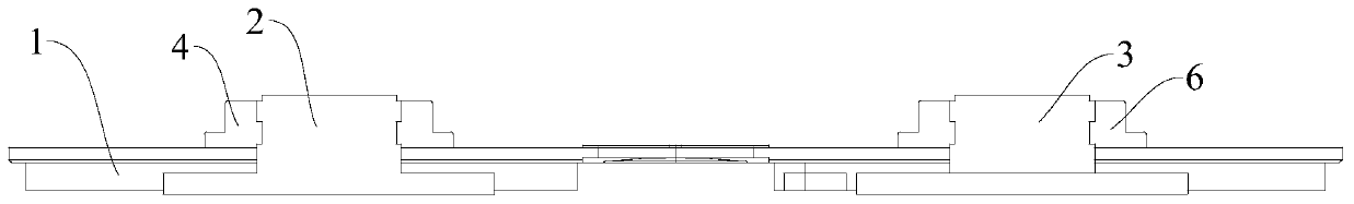
[0060] Refer below Figure 1-Figure 3 A power battery cover plate according to a specific embodiment of the present invention is described.

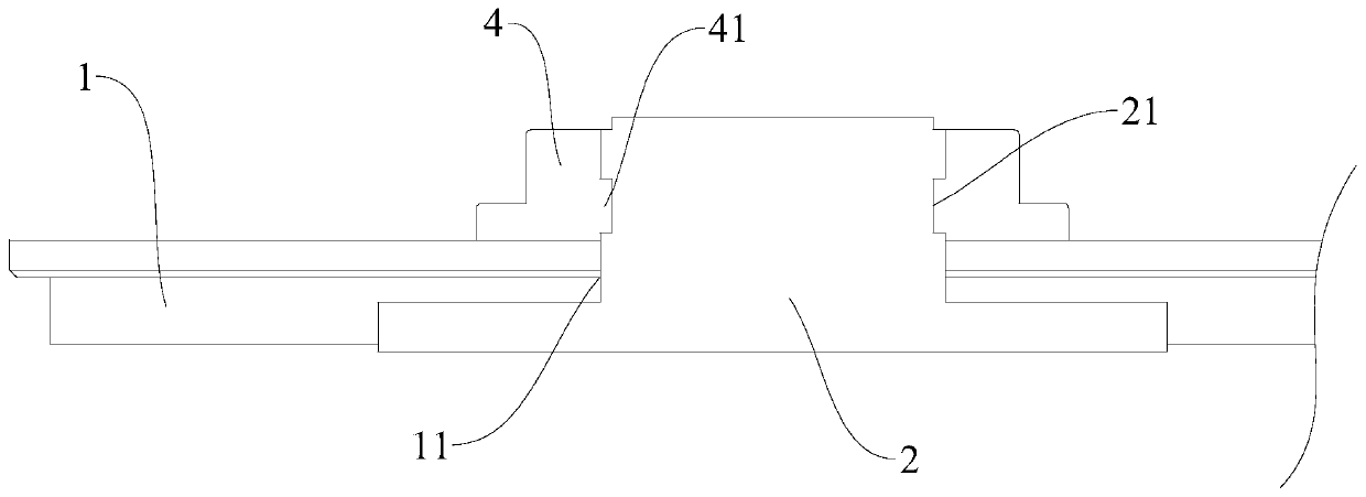
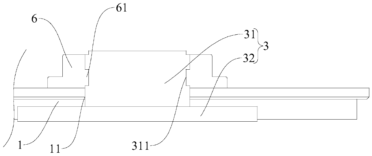
[0061] like Figure 1-Figure 3 As shown, the power battery cover plate of this embodiment includes a top cover 1, a positive pole 2 and a negative pole 3, the top cover 1 is provided with two through holes 11, and the positive pole 2 and the negative pole 3 are respectively installed in the two through holes. Inside hole 11. The positive pole 2 is an aluminum pole, the negative pole 3 includes an aluminum part 31 and a copper part 32 , the copper part 32 fits on the big end of the through hole 11 , and the aluminum part 31 fits on the small end of the through hole 11 .

[0062] The positive pole 2 is connected to the top cover 1 through the positive pole injection molded part 4. The positive pole pole 2 is provided with a positive pole groove 21. The positive pole groove 21 extends along the circumferential direction of the positive po...

Embodiment 2

[0064] Refer below Figure 4-Figure 6 A power battery cover plate according to another specific embodiment of the present invention is described.

[0065] like Figure 4-Figure 6 As shown, the power battery cover plate of this embodiment includes a top cover 1, a positive pole 2 and a negative pole 3, the top cover 1 is provided with two through holes 11, and the positive pole 2 and the negative pole 3 are respectively installed in the two through holes. Inside hole 11. The positive pole 2 is an aluminum pole, the negative pole 3 includes an aluminum part 31 and a copper part 32 , the copper part 32 fits on the big end of the through hole 11 , and the aluminum part 31 fits on the small end of the through hole 11 .

[0066] The positive column 2 is riveted on the top cover 1 through the positive pressing block 5, the positive pressing block 5 includes a first pressing block 51 and a first insulator 52, the first pressing block 51 is sleeved on the positive pole 2, and the pos...

Embodiment 3

[0069] like Figure 9-Figure 11 A power battery cover plate according to another specific embodiment of the present invention is described.

[0070] The structure of the power battery cover plate of this embodiment is substantially the same as that of Embodiment 2, the difference is that the first pressing block 51 of this embodiment is directly fitted into the first groove 521 of the first insulating member 52, and the second The two pressing blocks 71 are directly engaged in the second groove 721 of the second insulating member 72 .


PUM


Abstract

The invention discloses a power battery cover plate. The power battery cover plate comprises a top cover, a positive pole and a negative pole. The positive pole is an aluminum pole. The positive poleis connected to the top cover through a positive injection molding part or riveted to the top cover through a positive pressing block. The negative pole comprises an aluminum part and a copper part, one part of the aluminum part penetrates out of the upper side wall of the top cover, the copper part is located on the lower portion of the top cover, and the negative pole is connected to the top cover through a negative injection molding part or riveted to the top cover through a negative pressing block. According to the power battery cover plate, the part, exposed out of the top cover, of the negative pole column is prevented from being seriously oxidized, the service life of the negative pole column and the whole power battery cover plate is prolonged, the connecting structure between thepole column and the top cover is simplified, the positive pole column and the negative pole column are convenient to install, and the mass of the whole power battery cover plate is reduced.

Description

technical field [0001] The invention relates to the technical field of power batteries, in particular to a power battery cover plate. Background technique [0002] In the existing power battery cover, the positive pole and the negative pole are usually installed by means of snap springs, the installation stability is poor, and the weight of the entire power battery cover is relatively large. In addition, most of the existing negative poles are copper structures. Although the negative poles can ensure good electrical conductivity, the weight of the negative poles made of pure copper increases the weight of the entire power battery cover, and the pure copper is exposed to the outside for a long time It is prone to corrosion and affects electrical performance. Contents of the invention [0003] The purpose of the present invention is to provide a cover plate for a power battery, which is light in weight, good in stability, low in cost and long in service life. [0004] In o...

Claims


Application Information

Patent Timeline
Patent Type & Authority Applications(China)
IPC IPC(8): H01M2/30H01M2/32H01M2/04H01M50/147H01M50/543H01M50/571
CPCH01M50/147H01M50/571H01M50/543Y02E60/10
Inventor 励建炬张中涛
Owner SHENZHEN KEDALI IND CO LTD
Why Eureka
Try Eureka